 |
am2zzw00003844
DTC U0028:81/U0028:83/U0028:87 [BCM]
id0902f5341100
Malfunction Location
Vehicles with advanced keyless and start system
Vehicles with keyless entry system
Detection Condition
Vehicles with advanced keyless and start system
Vehicles with keyless entry system
Possible Causes
Vehicles with advanced keyless and start system
Vehicles with keyless entry system
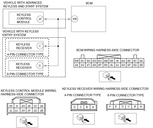
System Wiring Diagram
am2zzw00003844
|
Diagnostic Procedure
Vehicles with advanced keyless and start system
|
Step |
Inspection |
Action |
|
|---|---|---|---|
|
1
|
PERFORM DTC INSPECTION
• Clear DTCs using the M-MDS.
(See CLEARING DTC [BCM].)
• Lock and unlock the doors using the transmitter.
• Perform the BCM DTC inspection using the M-MDS.
(See DTC INSPECTION [BCM].)
• Are DTCs U0028:81, U0028:83, U0028:87 displayed?
|
Yes
|
Go to the next step.
|
|
No
|
DTC troubleshooting completed.
|
||
|
2
|
VERIFY KEYLESS CONTROL MODULE CONNECTOR CONDITION
• Disconnect the negative and positive battery cables.
• Disconnect the keyless control module connector.
• Inspect the connection condition and wiring harness.
• Are the connector terminals normal without damage, deformation, corrosion, or disconnection?
|
Yes
|
Go to the next step.
|
|
No
|
Repair or replace the connector, then go to the final step.
|
||
|
3
|
VERIFY KEYLESS CONTROL MODULE CONNECTOR CONDITION
• Remove the keyless control module.
• Inspect the keyless control module.
• Is the keyless control module normal?
|
Yes
|
Go to the next step.
|
|
No
|
Replace the keyless control module, then go to the final step.
|
||
|
4
|
VERIFY BCM CONNECTOR CONDITION
• Disconnect the BCM connector.
• Inspect the connection condition and wiring harness.
• Are the connector terminals normal without damage, deformation, corrosion, or disconnection?
|
Yes
|
Go to the next step.
|
|
No
|
Repair or replace the connector, then go to the final step.
|
||
|
5
|
VERIFY WIRING HARNESS BETWEEN KEYLESS CONTROL MODULE AND BCM FOR SHORT TO GROUND
• Inspect for continuity between BCM terminal 6W and body ground.
• Is there continuity?
|
Yes
|
Repair or replace the related wiring harness, then go to the final step.
|
|
No
|
Go to the next step.
|
||
|
6
|
VERIFY WIRING HARNESS BETWEEN KEYLESS CONTROL MODULE AND BCM FOR OPEN CIRCUIT
• Inspect for continuity between keyless control module terminal 2F and BCM terminal 6W.
• Is there continuity?
|
Yes
|
Go to the next step.
|
|
No
|
Repair or replace the related wiring harness, then go to the final step.
|
||
|
7
|
VERIFY WIRING HARNESS BETWEEN KEYLESS CONTROL MODULE AND BCM FOR SHORT TO POWER SUPPLY
• Measure the voltage between BCM terminal 6W and body ground.
• Is there B+?
|
Yes
|
Repair or replace the related wiring harness, then go to the final step.
|
|
No
|
Go to the next step.
|
||
|
8
|
VERIFY TROUBLESHOOTING COMPLETED
• Connect all the connectors.
• Connect the battery cable.
• Clear DTCs using the M-MDS.
(See CLEARING DTC [BCM].)
• Lock and unlock the doors using the transmitter.
• Perform the BCM DTC inspection using the M-MDS.
(See DTC INSPECTION [BCM].)
• Are DTCs U0028:81, U0028:83, U0028:87 displayed?
|
Yes
|
Replace the BCM.
|
|
No
|
DTC troubleshooting completed.
|
||
Vehicles with Keyless Entry System
|
Step |
Inspection |
Action |
|
|---|---|---|---|
|
1
|
PERFORM DTC INSPECTION
• Clear DTCs using the M-MDS.
(See CLEARING DTC [BCM].)
• Lock and unlock the doors using the transmitter.
• Perform the BCM DTC inspection using the M-MDS.
(See DTC INSPECTION [BCM].)
• Are DTCs U0028:81, U0028:83, U0028:87 displayed?
|
Yes
|
Go to the next step.
|
|
No
|
DTC troubleshooting completed.
|
||
|
2
|
VERIFY KEYLESS RECEIVER CONNECTOR CONDITION
• Disconnect the negative and positive battery cables.
• Disconnect the keyless receiver connector (RH).
• Inspect the connection condition and wiring harness.
• Are the connector terminals normal without damage, deformation, corrosion, or disconnection?
|
Yes
|
Go to the next step.
|
|
No
|
Repair or replace the connector, then go to the final step.
|
||
|
3
|
VERIFY KEYLESS RECEIVER CONDITION
• Remove the keyless receiver.
• Inspect the keyless receiver.
• Is the keyless receiver normal?
|
Yes
|
Go to the next step.
|
|
No
|
Replace the keyless receiver, then go to the final step.
|
||
|
4
|
VERIFY BCM CONNECTOR CONDITION
• Disconnect the BCM connector.
• Inspect the connection condition and wiring harness.
• Are the connector terminals normal without damage, deformation, corrosion, or disconnection?
|
Yes
|
Go to the next step.
|
|
No
|
Repair or replace the connector, then go to the final step.
|
||
|
5
|
VERIFY WIRING HARNESS BETWEEN KEYLESS RECEIVER AND BCM FOR SHORT TO GROUND
• Inspect for continuity between BCM terminal 6W and body ground.
• Is there continuity?
|
Yes
|
Repair or replace the related wiring harness, then go to the final step.
|
|
No
|
Go to the next step.
|
||
|
6
|
VERIFY BETWEEN KEYLESS RECEIVER AND BCM FOR OPEN CIRCUIT
• Inspect for continuity between keyless receiver (4-pin connector type) terminal C/keyless receiver (6-pin connector type) terminal D and BCM terminal 6W.
• Is there continuity?
|
Yes
|
Go to the next step.
|
|
No
|
Repair or replace the related wiring harness, then go to the final step.
|
||
|
7
|
VERIFY WIRING HARNESS BETWEEN KEYLESS RECEIVER AND BCM FOR SHORT TO POWER SUPPLY
• Measure the voltage between BCM terminal 6W and body ground.
• Is there B+?
|
Yes
|
Repair or replace the related wiring harness, then go to the final step.
|
|
No
|
Go to the next step.
|
||
|
8
|
VERIFY TROUBLESHOOTING COMPLETED
• Connect all the connectors.
• Connect the battery cable.
• Clear DTCs using the M-MDS.
(See CLEARING DTC [BCM].)
• Lock and unlock the doors using the transmitter.
• Perform the BCM DTC inspection using the M-MDS.
(See DTC INSPECTION [BCM].)
• Are DTCs U0028:81, U0028:83, U0028:87 displayed?
|
Yes
|
Replace the BCM.
|
|
No
|
DTC troubleshooting completed.
|
||