 |
am2zzw00003819
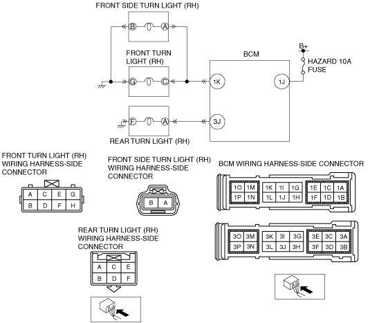
DTC B1D07:15 [BCM]
id0902f5389500
Malfunction Location
Detection Condition
Possible Causes
System Wiring Diagram
am2zzw00003819
|
Diagnostic Procedure
|
Step |
Inspection |
Action |
|
|---|---|---|---|
|
1
|
PERFORM DTC INSPECTION
• Clear DTCs using the M-MDS.
(See CLEARING DTC [BCM].)
• Turn the turn switch on.
• Perform the BCM DTC inspection using the M-MDS.
(See DTC INSPECTION [BCM].)
• Is DTC B1D07:15 displayed?
|
Yes
|
Go to the next step.
|
|
No
|
DTC troubleshooting completed.
|
||
|
2
|
PERFORM INSPECTION OF FRONT TURN LIGHT (RH), REAR TURN LIGHT (RH), AND FRONT SIDE TURN LIGHT (RH)
• Disconnect the negative and positive battery cables.
• Inspect the front turn light (RH), rear turn light (RH), and front side turn light (RH).
• Is the bulb normal?
|
Yes
|
Go to the next step.
|
|
No
|
Replace the bulb, then go to the final step.
|
||
|
3
|
VERIFY FRONT TURN LIGHT (RH) CONNECTOR CONDITION
• Disconnect the negative battery cable.
• Disconnect the front turn light connector (RH).
• Inspect the connection condition and wiring harness.
• Are the connector terminals normal without damage, deformation, corrosion, or disconnection?
|
Yes
|
Go to the next step.
|
|
No
|
Repair or replace the connector, then go to the final step.
|
||
|
4
|
VERIFY WIRING HARNESS BETWEEN FRONT TURN LIGHT (RH) AND BODY GROUND FOR OPEN CIRCUIT
• Inspect for continuity between front turn light (RH) terminal G and body ground.
• Is there continuity?
|
Yes
|
Go to the next step.
|
|
No
|
Repair or replace the related wiring harness, then go to the final step.
|
||
|
5
|
VERIFY FRONT SIDE TURN LIGHT (RH) CONNECTOR CONDITION
• Disconnect the negative battery cable.
• Disconnect the front side turn light connector (RH).
• Inspect the connection condition and wiring harness.
• Are the connector terminals normal without damage, deformation, corrosion, or disconnection?
|
Yes
|
Go to the next step.
|
|
No
|
Repair or replace the connector, then go to the final step.
|
||
|
6
|
VERIFY WIRING HARNESS BETWEEN FRONT SIDE TURN LIGHT (RH) AND BODY GROUND FOR OPEN CIRCUIT
• Inspect for continuity between front side turn light (RH) terminal B and body ground.
• Is there continuity?
|
Yes
|
Go to the next step.
|
|
No
|
Repair or replace the related wiring harness, then go to the final step.
|
||
|
7
|
VERIFY REAR TURN LIGHT (RH) CONNECTOR CONDITION
• Disconnect the negative battery cable.
• Disconnect the rear turn light connector (RH).
• Inspect the connection condition and wiring harness.
• Are the connector terminals normal without damage, deformation, corrosion, or disconnection?
|
Yes
|
Go to the next step.
|
|
No
|
Repair or replace the connector, then go to the final step.
|
||
|
8
|
VERIFY WIRING HARNESS BETWEEN REAR TURN LIGHT (RH) AND BODY GROUND FOR OPEN CIRCUIT
• Inspect for continuity between rear turn light (RH) terminal F and body ground.
• Is there continuity?
|
Yes
|
Go to the next step.
|
|
No
|
Repair or replace the related wiring harness, then go to the final step.
|
||
|
9
|
VERIFY BCM CONNECTOR CONDITION
• Disconnect the BCM connector.
• Inspect the connection condition and wiring harness.
• Are the connector terminals normal without damage, deformation, corrosion, or disconnection?
|
Yes
|
Go to the next step.
|
|
No
|
Repair or replace the connector, then go to the final step.
|
||
|
10
|
VERIFY WIRING HARNESS BETWEEN FRONT TURN LIGHT (RH), FRONT SIDE TURN LIGHT (RH), REAR TURN LIGHT (RH) AND BCM FOR OPEN CIRCUIT
• Inspect for continuity between the following wiring terminals.
• Is there continuity?
|
Yes
|
Go to the next step.
|
|
No
|
Repair or replace the related wiring harness, then go to the final step.
|
||
|
11
|
VERIFY WIRING HARNESS BETWEEN FRONT TURN LIGHT (RH), FRONT SIDE TURN LIGHT (RH), REAR TURN LIGHT (RH) AND BCM FOR SHORT TO POWER SUPPLY
• Measure the voltage between the following wiring terminals.
• Is there B+?
|
Yes
|
Repair or replace the related wiring harness, then go to the final step.
|
|
No
|
Go to the next step.
|
||
|
12
|
VERIFY TROUBLESHOOTING COMPLETED
• Connect all the connectors.
• Connect the battery cable.
• Clear DTCs using the M-MDS.
(See CLEARING DTC [BCM].)
• Turn the turn switch on.
• Perform the BCM DTC inspection using the M-MDS.
(See DTC INSPECTION [BCM].)
• Is DTC B1D07:15 displayed?
|
Yes
|
Replace the BCM.
|
|
No
|
DTC troubleshooting completed.
|
||