 |
am2zzw00002538
DTC U3003:16, U3003:17 [THEFT-DETERRENT SYSTEM]
id0902g7850900
Detection Condition
Possible Causes
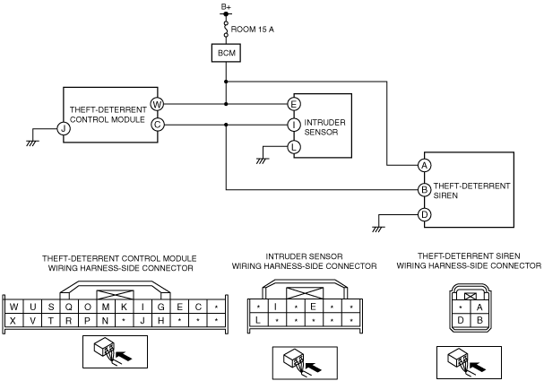
System Wiring Diagram
am2zzw00002538
|
Diagnostic Procedure
|
Step |
Inspection |
Action |
|
|---|---|---|---|
|
1
|
FUSE INSPECTION
• Turn the ignition switch to the LOCK position.
• Disconnect the negative battery cable.
• Remove the ROOM 15 A fuse.
• Is the fuse normal?
|
Yes
|
Go to the next step.
|
|
No
|
Replace the fuse.
|
||
|
2
|
BATTERY INSPECTION
• Measure the battery positive voltage.
• Is the voltage between 9—16 V?
|
Yes
|
Go to the next step.
|
|
No
|
Higher than specification
• Replace or inspection the battery.
(See BATTERY INSPECTION [ZJ, ZY].)
• Go to Step 4.
Lower than specification
• Replace or charge the battery.
(See BATTERY RECHARGING [ZJ, ZY].)
• Go to Step 4.
|
||
|
3
|
INSPECT WIRING HARNESS BETWEEN BATTERY AND THEFT-DETERRENT CONTROL MODULE
• Disconnect the theft-deterrent control module connector.
• Inspect the wiring harness between the battery and theft-deterrent control module connector terminal W for the following:
• Is the wiring harness normal?
|
Yes
|
Go to the next step.
|
|
No
|
Repair or replace the wiring harness between the battery and the theft-deterrent control module.
|
||
|
4
|
INSPECT BCM
• Reconnect the disconnected connectors.
• Connect the negative battery cable.
• Turn the ignition switch to the ON position.
• Measure the voltage of BCM connector terminal 3P.
• Is the wiring harness normal?
|
Yes
|
Go to the next step.
|
|
No
|
Replace the BCM.
|
||
|
5
|
VERIFY DTCs
• Clear DTCs using the M-MDS.
• Verify DTCs using the M-MDS.
• Is DTC U3003:16, U3003:17 displayed?
|
Yes
|
Replace the theft-deterrent control module.
|
|
No
|
DTC troubleshooting completed.
|
||