|
1
|
VERIFY RELATED SERVICE INFORMATION AVAILABILITY
• Verify related Service Information availability.
• Is any related Service Information available?
|
Yes
|
Perform repair or diagnosis according to the available Service Information.
• If the vehicle is not repaired, go to the next step.
|
|
No
|
Go to the next step.
|
|
2
|
INSPECT CURRENT SENSOR CONNECTOR CONDITION
• Turn the ignition switch off.
• Disconnect the current sensor connector.
• Inspect for poor connection (such as damaged/pulled-out pins, corrosion).
• Is there any malfunction?
|
Yes
|
Repair or replace the connector and/or terminals, then go to Step 9.
|
|
No
|
Go to the next step.
|
|
3
|
INSPECT CURRENT SENSOR CIRCUIT FOR SHORT TO GROUND
• Current sensor connector is disconnected.
• Inspect for continuity between the following terminals (wiring harness-side) and body ground:
-
― Current sensor terminal A
― Current sensor terminal C
• Is there continuity?
|
Yes
|
If the short to ground circuit could be detected:
• Repair or replace the wiring harness for a possible short to ground.
If the short to ground circuit could not be detected:
• Replace the PCM (short to ground in the PCM internal circuit).
Go to Step 9.
|
|
No
|
Go to the next step.
|
|
4
|
INSPECT PCM CONNECTOR CONDITION
• Disconnect the PCM connector.
• Inspect for poor connection (such as damaged/pulled-out pins, corrosion).
• Is there any malfunction?
|
Yes
|
Repair or replace the connector and/or terminals, then go to Step 9.
|
|
No
|
Go to the next step.
|
|
5
|
INSPECT CURRENT SENSOR SIGNAL CIRCUIT FOR SHORT TO POWER SUPPLY
• Current sensor and PCM connectors are disconnected.
• Turn the ignition switch to the ON position (engine off).
• Measure the voltage at the current sensor terminal C (wiring harness-side).
• Is there any voltage?
|
Yes
|
Repair or replace the wiring harness for a possible short to power supply, then go to Step 9.
|
|
No
|
Go to the next step.
|
|
6
|
INSPECT CURRENT SENSOR CIRCUITS FOR SHORT TO EACH OTHER
• Current sensor and PCM connectors are disconnected.
• Turn the ignition switch off.
• Inspect for continuity between current sensor terminals A, C and B (wiring harness-side).
• Is there continuity?
|
Yes
|
Repair or replace the wiring harness for a possible short to each other, then go to Step 9.
|
|
No
|
Go to the next step.
|
|
7
|
INSPECT CURRENT SENSOR CIRCUIT FOR OPEN CIRCUIT
• Current sensor and PCM connectors are disconnected.
• Inspect for continuity between the following terminals (wiring harness-side):
-
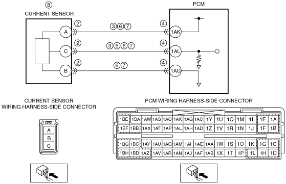
― Current sensor terminal A—PCM terminal 1AK
― Current sensor terminal C—PCM terminal 1AL
― Current sensor terminal B—PCM terminal 1AG
• Is there continuity?
|
Yes
|
Go to the next step.
|
|
No
|
Repair or replace the wiring harness for a possible open circuit, then go to Step 9.
|
|
8
|
INSPECT CURRENT SENSOR
• Reconnect all disconnected connectors.
• Inspect the current sensor.
• Is there any malfunction?
|
Yes
|
Replace the current sensor, then go to the next step.
|
|
No
|
Go to the next step.
|
|
9
|
VERIFY DTC TROUBLESHOOTING COMPLETED
• Make sure to reconnect all disconnected connectors.
• Clear the DTC from the PCM memory using the M-MDS.
• Perform the KOEO or KOER self test.
• Is the same DTC present?
|
Yes
|
Repeat the inspection from Step 1.
• If the malfunction recurs, replace the PCM.
Go to the next step.
|
|
No
|
Go to the next step.
|
|
10
|
VERIFY AFTER REPAIR PROCEDURE
• Perform the “AFTER REPAIR PROCEDURE”.
• Are any DTCs present?
|
Yes
|
Go to the applicable DTC inspection.
|
|
No
|
DTC troubleshooting completed.
|