 |
am2zzw00005266
FUEL TANK REMOVAL/INSTALLATION [MZR 1.3, MZR 1.5]
id011417801600
1. Level the vehicle.
2. Complete the “BEFORE SERVICE PRECAUTION”. (See BEFORE SERVICE PRECAUTION [MZR 1.3, MZR 1.5].)
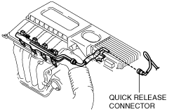
3. Disconnect the quick release connector. (See QUICK RELEASE CONNECTOR REMOVAL/INSTALLATION [MZR 1.3, MZR 1.5].)
am2zzw00005266
|
4. Connect a long hose to the disconnected quick release connector and drain the fuel into a container used for collecting gasoline.
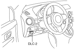
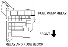
5. Drain the fuel from the fuel tank using the following procedure:
am2zzw00001288
|
am2zzw00005267
|
am2zzw00005268
|
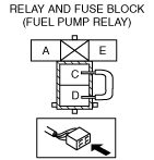
6. Stop the fuel pump using the following procedure.
7. Remove the rear seat cushion. (See REAR SEAT CUSHION REMOVAL/INSTALLATION.)
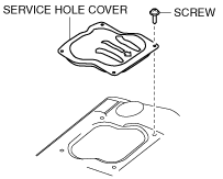
8. Remove the service hole cover.
am2zzw00005269
|
9. Disconnect the fuel pump unit connector.
10. Disconnect the quick release connector. (See QUICK RELEASE CONNECTOR REMOVAL/INSTALLATION [MZR 1.3, MZR 1.5].)
11. Remove the tunnel member. (See EXHAUST SYSTEM REMOVAL/INSTALLATION [MZR 1.3, MZR 1.5].)
12. Remove the TWC. (See EXHAUST SYSTEM REMOVAL/INSTALLATION [MZR 1.3, MZR 1.5].)
13. Remove the insulator No.2. (See EXHAUST SYSTEM REMOVAL/INSTALLATION [MZR 1.3, MZR 1.5].)
14. Remove in the order indicated in the table.
15. Install in the reverse order of removal.
16. Complete the “AFTER SERVICE PRECAUTION”. (See AFTER SERVICE PRECAUTION [MZR 1.3, MZR 1.5].)
am2zzw00005270
|
|
1
|
Quick release connector
|
|
2
|
Fuel tank component
|
|
3
|
Joint hose
(See Joint Hose Installation Note.)
|
|
4
|
Breather hose
|
|
5
|
Charcoal canister
|
|
6
|
Fuel pump unit
|
|
7
|
Fuel-filler cap
|
|
8
|
Fuel-filler cap cover
|
|
9
|
O-ring
|
|
10
|
Dust cover
|
|
11
|
Fuel-filler pipe
|
Fuel Tank Component Removal Note
1. Disconnect the joint hose (fuel-filler pipe side).
2. Disconnect the breather hose (fuel-filler pipe side).
3. Set the parking cable out of the way.
4. Remove the fuel tank component.
Fuel-filler Pipe Removal Note
1. Remove the splash shield (LH). (See SPLASH SHIELD REMOVAL/INSTALLATION.)
2. Remove the rear mudguard (LH). (See MUDGUARD REMOVAL/INSTALLATION.)
3. Remove the fuel-filler pipe.
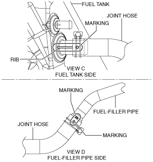
Joint Hose Installation Note
1. Connect the joint hose as shown in the figure.
am2zzw00005271
|
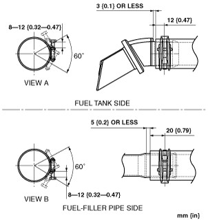
2. Install the joint hose and clamp as shown in the figure.
am2zzw00005272
|
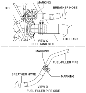
Breather Hose Installation Note
1. Connect the breather hose as shown in the figure.
am2zzw00005273
|
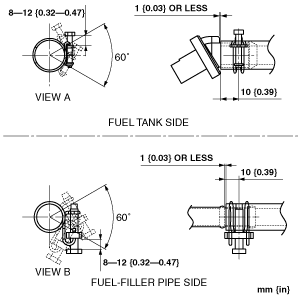
2. Install the breather hose and clamp as shown in the figure.
am2zzw00005274
|