 |
am3zzw00008722
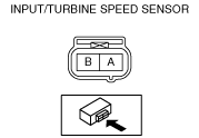
INPUT/TURBINE SPEED SENSOR INSPECTION [DJVA-EL]
id051901286400
Off-Vehicle Inspection
1. Disconnect the negative battery cable.
2. Remove the input/turbine speed sensor. (See INPUT/TURBINE SPEED SENSOR REMOVAL/INSTALLATION [DJVA-EL].)
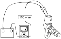
3. Connect the input/turbine speed sensor terminal B to the battery positive terminal, connect the battery negative terminal to input/turbine speed sensor terminal A through an ammeter set to a resistance of 100 ohm.
am3zzw00008722
|
am3zzw00008457
|
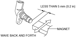
4. Wave a magnet back and forth over the top of the input/turbine speed sensor (less than 5 mm {0.2 in}).
am3zzw00008458
|
5. Inspect the HIGH and LOW signal current values which change by waving the magnetic.
Input/turbine speed sensor specification
|
Signal |
Voltage (V) |
|---|---|
|
High
|
12.0—16.0
|
|
Low
|
4.0—8.0
|
Wiring Harness Inspection
1. Disconnect the negative battery cable.
2. Remove the dashboard under cover. (See DASHBOARD UNDER COVER REMOVAL/INSTALLATION.)
3. Remove the front side garnish. (See FRONT SIDE GARNISH REMOVAL/INSTALLATION.)
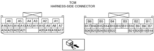
4. Disconnect the TCM connector.
5. Inspect the wiring harness between the input/turbine speed sensor and the TCM using a tester.
am3zzw00008265
|
Input/turbine speed sensor specification
|
Terminal |
Continuity |
|---|---|
|
B5—ground
|
No continuity
|
|
B14—ground
|
No continuity
|