 |
adejjw00000675
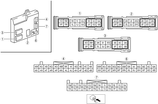
BODY CONTROL MODULE (BCM) INSPECTION
id094000800300
1. Remove the dashboard under cover. (See DASHBOARD UNDER COVER REMOVAL/INSTALLATION.)
2. Remove the glove compartment. (See GLOVE COMPARTMENT REMOVAL/INSTALLATION.)
3. Measure the voltage at each terminal and inspect for the continuity between the terminals and ground is as indicated in the Terminal Voltage Tables (Reference).
Terminal Voltage Table (Reference)
adejjw00000675
|
|
Terminal |
Signal |
Connected to |
Measurement condition |
Voltage (V) |
Inspection item (s) |
|
|---|---|---|---|---|---|---|
|
1A
|
Windshield wiper signal
|
Windshield wiper motor
|
Ignition switch at ON
|
B+
|
• Windshield wiper motor
• Related wiring harness
|
|
|
Ignition switch at off
|
1.0 or less
|
|||||
|
1B
|
Windshield wiper (HI) signal
|
Windshield wiper motor
|
Ignition switch at ON
|
Windshield wiper operating at HI
|
B+
|
• Windshield wiper motor
• Related wiring harness
|
|
OFF
|
1.0 or less
|
|||||
|
1C
|
Rear window defroster power supply
|
R.DEF 20 A fuse
|
Under any condition
|
B+
|
• R.DEF 20A fuse
• Related wiring harness
|
|
|
1D
|
Windshield wiper (Lo) signal
|
Windshield wiper motor
|
Ignition switch at ON
|
Windshield wiper operating at Lo
|
B+
|
• Windshield wiper motor
• Related wiring harness
|
|
Windshield wiper not operating
|
1.0 or less
|
|||||
|
1E
|
TNS power supply
|
TAIL 15 A fuse
|
Under any condition
|
B+
|
• TAIL 15A fuse
• Related wiring harness
|
|
|
1F
|
Windshield wiper auto stop signal
|
Windshield wiper motor
|
Ignition switch at ON
|
Windshield wiper operating
|
B+
|
• Windshield wiper motor
• Related wiring harness
|
|
Windshield wiper not operating
|
1.0 or less
|
|||||
|
1G
|
Front TNS inhibited
|
Parking light
|
TNS ON
|
B+
|
• Parking light
• Related wiring harness
|
|
|
TNS OFF
|
1.0 or less
|
|||||
|
1H
|
Windshield washer motor control
|
Washer motor
|
Ignition switch at ON
|
Windshield washer motor operating
|
B+
|
• Washer motor
• Related wiring harness
|
|
Windshield washer motor not operating
|
1.0 or less
|
|||||
|
1I
|
Hazard power supply
|
HAZARD 10A fuse
|
Under any condition
|
B+
|
• HAZARD 10A fuse
• Related wiring harness
|
|
|
1J
|
Rear window washer motor control
|
Washer motor
|
Ignition switch at ON
|
Rear washer motor operating
|
B+
|
• Washer motor
• Related wiring harness
|
|
Rear washer motor not operating
|
1.0 or less
|
|||||
|
1K
|
Front turn light (RH) control
|
• Front turn light (RH)
• Front side turn light (RH)
|
Turn switch (RH) on
|
Front turn light (RH) flashes
|
Alternates between 1.0 or less and B+
|
• Front turn light (RH)
• Front side turn light (RH)
• Related wiring harness
|
|
Hazard warning switch on
|
||||||
|
Front turn light (RH) not illuminated
|
1.0 or less
|
|||||
|
1L
|
Front turn light (LH) control
|
• Front turn light (LH)
• Front side turn light (LH)
|
Turn switch (LH) on
|
Front turn light (LH) flashes
|
Alternates between 1.0 or less and B+
|
• Front turn light (LH)
• Front side turn light (LH)
• Related wiring harness
|
|
Hazard warning switch on
|
||||||
|
Front turn light (LH) not illuminated
|
1.0 or less
|
|||||
|
1M
|
—
|
—
|
—
|
—
|
—
|
|
|
1N
|
—
|
—
|
—
|
—
|
—
|
|
|
1O
|
Interior light power supply
|
ROOM 15 A fuse
|
Under any condition
|
B+
|
• ROOM 15 A fuse
• Related wiring harness
|
|
|
1P
|
Door lock power supply
|
D/L 20 A fuse
|
Under any condition
|
B+
|
• D/L 20 A fuse
• Related wiring harness
|
|
|
2A
|
—
|
—
|
—
|
—
|
—
|
|
|
2B
|
—
|
—
|
—
|
—
|
—
|
|
|
2C
|
—
|
—
|
—
|
—
|
—
|
|
|
2D
|
Ground signal
|
Body ground
|
Under any condition
|
1.0 or less
|
Related wiring harness
|
|
|
2E
|
—
|
—
|
—
|
—
|
—
|
|
|
2F
|
Rear window wiper power supply
(IG 2)
|
• R.WIP 10 A fuse
• Ignition switch
|
Ignition switch at ON
|
B+
|
• R.WIP 10 A fuse
• Ignition switch
• Related wiring harness
|
|
|
Ignition switch at off
|
1.0 or less
|
|||||
|
2G
|
Meter power supply
(IG 1)
|
• METER 10 A fuse
• Ignition switch
|
Ignition switch at ON
|
B+
|
• METER 10A fuse
• Ignition switch
• Related wiring harness
|
|
|
Ignition switch is off
|
1.0 or less
|
|||||
|
2H
|
Windshield washer switch signal
|
Wiper and washer switch
|
Ignition switch at ON
|
Windshield washer switch on
|
1.0 or less
|
• Wiper and washer switch
• Related wiring harness
|
|
Windshield washer switch off
|
B+
|
|||||
|
2I
|
—
|
—
|
—
|
—
|
—
|
|
|
2J
|
—
|
—
|
—
|
—
|
—
|
|
|
2K
|
—
|
—
|
—
|
—
|
—
|
|
|
2L
|
Rear window washer switch signal
|
Wiper and washer switch
|
Ignition switch at ON
|
Rear window washer switch on
|
1.0 or less
|
• Wiper and washer switch
• Related wiring harness
|
|
Rear window washer switch off
|
B+
|
|||||
|
2M
|
Signal ground
|
Body ground
|
Under any condition
|
1.0 or less
|
Related wiring harness
|
|
|
2N
|
Windshield wiper power supply
(IG 2)
|
• F.WIP 20 A fuse
• Ignition switch
|
Ignition switch at ON
|
B+
|
• F.WIP 20A fuse
• Ignition switch
• Related wiring harness
|
|
|
Ignition switch at off
|
1.0 or less
|
|||||
|
2O
|
Illumination output
|
• ILLUMI 7.5 A fuse
• Illumination light
|
TNS ON
|
B+
|
• ILLUMI 7.5 A fuse
• Illumination light
• Related wiring harness
|
|
|
TNS OFF
|
1.0 or less
|
|||||
|
2P
|
—
|
—
|
—
|
—
|
—
|
|
|
3A
|
Rear window defroster output
|
• Filament
• M.DEF 7.5 A fuse
|
Ignition switch at ON
|
Rear window defroster on
|
B+
|
• Filament
• M.DEF 7.5 A fuse
• Related wiring harness
|
|
Rear window defroster off
|
1.0 or less
|
|||||
|
3B
|
—
|
—
|
—
|
—
|
—
|
|
|
3C
|
Liftgate opener actuator power supply
|
Liftgate latch and lock actuator
|
Liftgate opener switch pressed, lock release operation
|
B+
|
• Liftgate latch and lock actuator
• Related wiring harness
|
|
|
Other
|
1.0 or less
|
|||||
|
3D
|
Rear window wiper power supply
|
Rear wiper motor
|
Ignition switch at ON
|
B+
|
• Rear wiper motor
• Related wiring harness
|
|
|
Ignition switch is off
|
1.0 or less
|
|||||
|
3E*6
|
Door lock control
|
Door lock actuators
|
Double locking system activated
|
1.0 or less → B+→ 1.0 or less
|
• Door lock actuators
• Related wiring harness
|
|
|
Other
|
1.0 or less
|
|||||
|
3F
|
Rear window wiper control
|
Rear wiper motor
|
Ignition switch at ON
|
Rear wiper activated
|
1.0 or less
|
• Rear motor
• Related wiring harness
|
|
Rear wiper not activated
|
B+
|
|||||
|
3G
|
—
|
—
|
—
|
—
|
||
|
3H
|
Rear TNS light signal
|
• Tail light
• License plate light
|
TNS ON
|
B+
|
• Tail light
• License plate light
• Related wiring harness
|
|
|
TNS OFF
|
1.0 or less
|
|||||
|
3I
|
Interior light control
|
Interior light
|
Interior light on by opening any door
|
Interior light off by closing all doors
|
Wave pattern (See Pattern 7.)
|
• Interior light
• Related wiring harness
|
|
3J
|
Rear turn light (RH) control
|
Rear turn light (RH)
|
Turn switch (RH) on
|
Rear turn light (RH) flashes
|
Alternates between 1.0 or less and B+
|
• Rear turn light (RH)
• Related wiring harness
|
|
Hazard warning switch on
|
||||||
|
Rear turn light (RH) not illuminated
|
1.0 or less
|
|||||
|
3K
|
—
|
—
|
—
|
—
|
—
|
|
|
3L
|
Rear turn light (LH) control
|
Rear turn light (LH)
|
Turn switch (LH) on
|
Rear turn light (LH) flashes
|
Alternates between 1.0 or less and B+
|
• Rear turn light (LH)
• Related wiring harness
|
|
Hazard warning switch on
|
||||||
|
Rear turn light (LH) not illuminated
|
1.0 or less
|
|||||
|
3M
|
Door lock control
|
Door lock actuators
|
Door lock actuator locking (without double locking system)
|
B+
|
• Door lock actuator
• Related wiring harness
|
|
|
Door lock actuator locking (with double locking system)
|
1.0 or less
|
|||||
|
Other
|
1.0 or less
|
|||||
|
3N
|
—
|
—
|
—
|
—
|
—
|
|
|
3O
|
Door unlock control
|
Door lock actuator
(Driver’s side)
|
Door lock actuator unlocking
|
B+
|
• Door lock actuator
• Related wiring harness
|
|
|
Other
|
1.0 or less
|
|||||
|
3P
|
Power supply
|
Interior light
|
Under any condition
|
B+
|
• Interior light
• Related wiring harness
|
|
|
4A
|
Brake fluid level signal
|
Brake fluid level sensor
|
Ignition switch at ON
|
Brake fluid level less than MIN
|
1.0 or less
|
• Brake fluid level sensor
• Related wiring harness
|
|
Brake fluid level above MIN.
|
5
|
|||||
|
4B*4
|
Oil pressure switch signal
|
Oil pressure switch
|
Engine running
|
B+
|
• Oil pressure switch
• Related wiring harness
|
|
|
Engine not running
|
1.0 or less
|
|||||
|
4C*3
|
Back-up light signal
|
Back-up light switch
|
Shift lever is in R position
|
B+
|
• Back-up light switch
• Related wiring harness
|
|
|
Shift lever is not in R position
|
1.0 or less
|
|||||
|
4D
|
—
|
—
|
—
|
—
|
—
|
|
|
4E
|
Rear fog light control (vehicles with rear fog light)
|
Rear fog light relay
|
Light switch at TNS position
|
Rear fog light switch ON
|
1.0 or less
|
• Rear fog light relay
• Related wiring harness
|
|
Rear fog light switch OFF
|
B+
|
|||||
|
4F
|
—
|
—
|
—
|
—
|
—
|
|
|
4G
|
Headlight low control (4-Beam Type Headlight)
|
Headlight relay (LO)
|
Headlights on
|
1.0 or less
|
• Headlight relay (LO)
• Related wiring harness
|
|
|
Headlights off
|
B+
|
|||||
|
4H
|
—
|
—
|
—
|
—
|
—
|
|
|
4I
|
Front fog light control
|
Front fog light relay
|
Light switch at TNS position
|
Front fog light switch ON
|
1.0 or less
|
• Front fog light relay
• Related wiring harness
|
|
Front fog light switch OFF
|
B+
|
|||||
|
4J
|
—
|
—
|
—
|
—
|
—
|
|
|
4K
|
—
|
—
|
—
|
—
|
—
|
|
|
4L
|
—
|
—
|
—
|
—
|
—
|
|
|
4M
|
Headlight low control (2-Beam Type Headlight)
|
Headlight relay (LO)
|
Light switch at LO position
|
1.0 or less
|
• Headlight relay (LO)
• Related wiring harness
|
|
|
Other
|
B+
|
|||||
|
4N
|
—
|
—
|
—
|
—
|
—
|
|
|
4O
|
Headlight high control
|
Headlight relay (HI)
|
Light switch at HEAD position
|
Light switch at HI or PASS position
|
1.0 or less
|
• Headlight relay (HI)
• Related wiring harness
|
|
Light switch at LO position
|
B+
|
|||||
|
4P
|
—
|
—
|
—
|
—
|
—
|
|
|
4Q
|
—
|
—
|
—
|
—
|
—
|
|
|
4R
|
—
|
—
|
—
|
—
|
—
|
|
|
4S
|
—
|
—
|
—
|
—
|
—
|
|
|
4T
|
—
|
—
|
—
|
—
|
—
|
|
|
4U
|
CAN_H
|
CAN system related module
|
Terminal used for communication therefore determination based on terminal voltage inspection not possible.
|
|||
|
4V
|
CAN_H
|
CAN system related module
|
Terminal used for communication therefore determination based on terminal voltage inspection not possible.
|
|||
|
4W
|
CAN_L
|
CAN system related module
|
Terminal used for communication therefore determination based on terminal voltage inspection not possible.
|
|||
|
4X
|
CAN_L
|
CAN system related module
|
Terminal used for communication therefore determination based on terminal voltage inspection not possible.
|
|||
|
6A
|
Turn switch input (RH)
|
Turn switch
|
Turn switch at RH position
|
1.0 or less
|
• Turn switch
• Related wiring harness
|
|
|
Turn switch at off position
|
Wave pattern (See Pattern 1.)
|
|||||
|
6B
|
Turn switch input (LH)
|
Turn switch
|
Turn switch at LH position
|
1.0 or less
|
• Turn switch
• Related wiring harness
|
|
|
Turn switch at off position
|
Wave pattern (See Pattern 1.)
|
|||||
|
6C
|
Rear wiper switch input (ON)
|
Wiper and washer switch
|
Rear wiper at on position
|
1.0 or less
|
• Wiper and washer switch
• Related wiring harness
|
|
|
Rear wiper at off position
|
Wave pattern (See Pattern 1.)
|
|||||
|
6D
|
Rear window defroster switch input
|
Climate control unit (rear window defroster switch)
|
Rear window defroster switch pressed and held
|
1.0 or less
|
• Climate control unit (rear window defroster switch)
• Related wiring harness
|
|
|
Rear window defroster switch not pressed
|
Wave pattern (See Pattern 1.)
|
|||||
|
6E
|
Headlight switch input (ON)
|
Light switch
|
Light switch in ON position
|
1.0 or less
|
• Light switch
• Related wiring harness
|
|
|
Light switch not at ON position
|
B+
|
|||||
|
6F
|
Windshield wiper switch input (HI)
|
Wiper and washer switch
|
Wiper switch in HI position
|
1.0 or less
|
• Wiper and washer switch
• Related wiring harness
|
|
|
Wiper switch not at HI position
|
Wave pattern (See Pattern 2.)
|
|||||
|
6G
|
Rear window defroster indicator signal
|
Climate control unit (rear window defroster indicator)
|
Ignition switch at ON
|
Rear window defroster indicator illuminated
|
1.0 or less
|
• Climate control unit (rear window defroster indicator)
• Related wiring harness
|
|
Rear window defroster indicator turned off
|
B+
|
|||||
|
6H
|
Sensitivity adjustment volume ground
|
Wiper and washer switch
|
Under any condition
|
1.0 or less
|
• Wiper and washer switch
• Related wiring harness
|
|
|
6I
|
Headlight switch input (HI)
|
Light switch
|
HI beam at passing position or lights on status
|
1.0 or less
|
• Light switch
• Related wiring harness
|
|
|
Except above
|
Wave pattern (See Pattern 2.)
|
|||||
|
6J
|
TNS switch signal
|
Light switch
|
TNS ON
|
1.0 or less
|
• Light switch
• Related wiring harness
|
|
|
TNS OFF
|
B+
|
|||||
|
6K
|
Headlight switch input (front fog light)
|
Light switch
|
Front fog light switch in on position
|
1.0 or less
|
• Light switch
• Related wiring harness
|
|
|
Front fog light switch in off position
|
Wave pattern (See Pattern 2.)
|
|||||
|
6L
|
Headlight switch input (vehicles with auto light/wiper system)
|
Light switch
|
Light switch at AUTO position
|
1.0 or less
|
• Light switch
• Related wiring harness
|
|
|
Light switch OFF position
|
Wave pattern (See Pattern 4.)
|
|||||
|
6M
|
Headlight switch input (vehicles with rear fog light)
|
Light switch
|
Rear fog light switch in on position
|
1.0 or less
|
• Light switch
• Related wiring harness
|
|
|
Rear fog light switch in off position
|
Wave pattern (See Pattern 2.)
|
|||||
|
6N
|
Windshield wiper switch input (Lo)
|
Wiper and washer switch
|
Ignition switch at ON
|
Windshield wiper switch LO position
|
1.0 or less
|
• Wiper and washer switch
• Related wiring harness
|
|
Windshield wiper switch off or INT position
|
B+
|
|||||
|
6O
|
Headlight switch input (LO)
|
Light switch
|
Light switch at LO position
|
1.0 or less
|
• Light switch
• Related wiring harness
|
|
|
Light switch at HI position
|
Wave pattern (See Pattern 2.)
|
|||||
|
Light switch at OFF or TNS position
|
B+
|
|||||
|
6P
|
Sensitivity adjustment volume
(Auto wiper only)
|
Wiper and washer switch
|
Sensitivity adjustment range for auto wiper turned from + position to - position
|
Switch position 1 position
|
Wave pattern (See 1 position.)
|
• Wiper and washer switch
• Related wiring harness
|
|
Switch position 2 position
|
Wave pattern (See 2 position.)
|
|||||
|
Switch position 3 position
|
Wave pattern (See 3 position.)
|
|||||
|
Switch position 4 position
|
Wave pattern (See 4 position.)
|
|||||
|
Switch position 5 position
|
Wave pattern (See 5 position.)
|
|||||
|
Switch position 6 position
|
0
|
|||||
|
6Q
|
Hazard warning switch signal
|
Hazard warning switch
|
Hazard warning switch on
|
1.0 or less
|
• Hazard warning switch
• Related wiring harness
|
|
|
Hazard warning switch off
|
Wave pattern (See Pattern 3.)
|
|||||
|
6R
|
Key reminder switch
|
Key reminder switch
|
Key inserted
|
B+
|
• Key reminder switch
• Related wiring harness
|
|
|
Key removed
|
1.0 or less
|
|||||
|
6S
|
Windshield wiper switch input
|
Wiper and washer switch
|
Ignition switch at ON
|
Wiper switch at off position
|
Wave pattern (See Pattern 1.)
|
• Wiper and washer switch
• Related wiring harness
|
|
Wiper switch at LO or HI position
|
Wave pattern (See Pattern 5.)
|
|||||
|
Wiper switch at INT position
|
1.0 or less
|
|||||
|
6T
|
—
|
—
|
—
|
—
|
—
|
|
|
6U*2
|
Liftgate opener switch input
|
Liftgate opener switch
|
Wave pattern (See Liftgate Opener Switch Input Signal Pulse (Reference) .)
|
• Liftgate opener switch
• Related wiring harness
|
||
|
6V
|
CAN_L
|
CAN system related module
|
Terminal used for communication therefore determination based on terminal voltage inspection not possible.
|
|||
|
6W
|
Serial communication
|
• Keyless receiver
• Instrument cluster
|
Terminal used for communication therefore determination based on terminal voltage inspection not possible.
|
|||
|
6X
|
CAN_H
|
CAN system related module
|
Terminal used for communication therefore determination based on terminal voltage inspection not possible.
|
|||
|
7A
|
Liftgate opener switch
|
Liftgate opener switch
|
Liftgate opener switch not pressed
|
1.0 or less
|
• Liftgate opener switch
• Related wiring harness
|
|
|
Liftgate opener switch pressed and held
|
Wave pattern*2 (See Liftgate Opener Switch Signal Pulse (Reference).)
|
|||||
|
approx. 3*1
|
||||||
|
7B
|
Parking brake switch signal
|
Parking brake switch
|
Ignition switch at ON
|
Parking brake applied
|
1.0 or less
|
• Parking brake switch
• Related wiring harness
|
|
Parking brake not applied
|
B+
|
|||||
|
7C
|
Key cylinder switch signal
|
Door key cylinder switch
|
Driver's door key cylinder rotated to lock direction
|
Wave pattern (See Pattern 6.)
|
• Door key cylinder switch
• Related wiring harness
|
|
|
Driver's door key cylinder rotated to unlock direction
|
1.0 or less
|
|||||
|
Driver’s door key cylinder at neutral position after rotating in lock or unlock direction
|
Wave pattern (See Pattern 1.)
|
|||||
|
7D
|
—
|
—
|
—
|
—
|
—
|
|
|
7E
|
All outer door handles
|
Power window main switch
|
Any door open
|
1.0 or less
|
• Power window main switch
• Related wiring harness
|
|
|
All doors closed
|
B+
|
|||||
|
7F
|
—
|
—
|
—
|
—
|
—
|
|
|
7G*5
|
Rear door latch switch (LH)
|
Rear door latch switch (LH)
|
Rear door (LH) open
|
Wave pattern (See Pattern 3.)
|
• Rear door latch switch (LH)
• Related wiring harness
|
|
|
Rear door (LH) closed
|
1.0 or less
|
|||||
|
7H
|
—
|
—
|
—
|
—
|
—
|
|
|
7I
|
Front door latch switch (driver side)
|
Front door latch switch (driver side)
|
Front door (driver side) open
|
Wave pattern (See Pattern 3.)
|
• Front door latch switch (driver side)
• Related wiring harness
|
|
|
Front door (driver side) closed
|
1.0 or less
|
|||||
|
7J
|
—
|
—
|
—
|
—
|
—
|
|
|
7K
|
Lock input (door lock-link switch)
|
Door lock-link switch (driver side)
|
Driver's door locked
|
1.0 or less
|
• Door lock-link switch (driver side)
• Related wiring harness
|
|
|
Driver's door unlocked
|
Wave pattern (See Pattern 3.)
|
|||||
|
7L
|
—
|
—
|
—
|
—
|
—
|
|
|
7M
|
Front door latch switch (passenger side)
|
Front door latch switch (passenger side)
|
Front door (passenger side) open
|
Wave pattern (See Pattern 3.)
|
• Front door latch switch (passenger side)
• Related wiring harness
|
|
|
Front door (passenger side) closed
|
1.0 or less
|
|||||
|
7N
|
—
|
—
|
—
|
—
|
—
|
|
|
7O*5
|
Rear door latch switch (RH)
|
Rear door latch switch (RH)
|
Rear door (RH) open
|
Wave pattern (See Pattern 3.)
|
• Rear door latch switch (RH)
• Related wiring harness
|
|
|
Rear door (RH) closed
|
1.0 or less
|
|||||
|
7P
|
—
|
—
|
—
|
—
|
—
|
|
|
7Q
|
Unlock input (door lock-link switch)
|
Door lock-link switch
|
Driver's door locked
|
Wave pattern (See Pattern 3.)
|
• Door lock-link switch
• Related wiring harness
|
|
|
Driver's door unlocked
|
1.0 or less
|
|||||
|
7R
|
—
|
—
|
—
|
—
|
—
|
|
|
7S
|
Liftgate switch signal
|
Liftgate switch
|
Liftgate opened
|
1.0 or less
|
• Liftgate switch
• Related wiring harness
|
|
|
Liftgate closed
|
B+
|
|||||
|
7T
|
—
|
—
|
—
|
—
|
—
|
|
|
7U
|
LIN communication
|
Rain sensor
|
Terminal used for communication therefore determination based on terminal voltage inspection not possible.
|
|||
|
7V
|
CAN_L
|
• CAN system related module
• DLC-2
|
Terminal used for communication therefore determination based on terminal voltage inspection not possible.
|
|||
|
7W
|
—
|
—
|
—
|
—
|
—
|
|
|
7X
|
CAN_H
|
• CAN system related module
• DLC-2
|
Terminal used for communication therefore determination based on terminal voltage inspection not possible.
|
|||
Generated pulse (reference)
Pattern 1
am2uuw00000733
|
Pattern 2
am2uuw00000734
|
Pattern 3
am2zzw00004149
|
Pattern 4
am2zzw00004146
|
Pattern 5
adejjw00005004
|
Pattern 6
am2zzw00004147
|
Pattern 7
am2uuw00000735
|
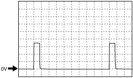
Liftgate Opener Switch Input Signal Pulse (Reference)
Liftgate opener switch not pressed
adejjw00005004
|
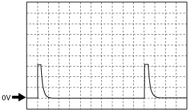
Liftgate opener switch pressed
adejjw00005005
|
Liftgate Opener Switch Signal Pulse (Reference)
adejjw00005005
|
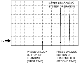
Door lock actuators 2-step unlocking (Reference)
am2uuw00000736
|
Sensitivity adjustment volume (Reference)
1 position
am2uuw00000834
|
2 position
am2uuw00000835
|
3 position
am2zzw00006277
|
4 position
am2uuw00000837
|
5 position
am2zzw00006278
|