 |
am3zzw00031984
FRONT LOWER ARM REMOVAL/INSTALLATION [(E)]
id0213008006x2
LH ATX(Except SKYACTIV-G 1.5 MTX/ATX)
1. Remove the wheel and tire. (See WHEEL AND TIRE REMOVAL/INSTALLATION.)
2. Remove the front under cover No.2. (See FRONT UNDER COVER No.2 REMOVAL/INSTALLATION.)
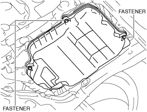
3. Remove the oil pan cover. (SKYACTIV-X 2.0)
am3zzw00031984
|
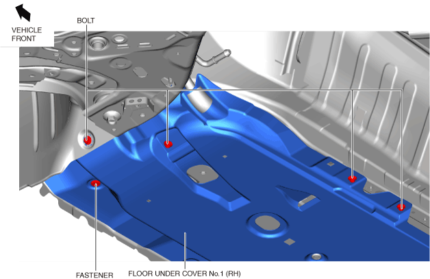
4. Remove the front under cover No.1. (See FRONT UNDER COVER No.1 REMOVAL/INSTALLATION.)
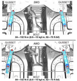
5. Remove the gusset.
am3zzw00031427
|
6. Remove the tunnel cover. (See EXHAUST SYSTEM REMOVAL/INSTALLATION [SKYACTIV-G (WITHOUT CYLINDER DEACTIVATION (E))].) (See EXHAUST SYSTEM REMOVAL/INSTALLATION [SKYACTIV-G (WITH CYLINDER DEACTIVATION (E))].) (See EXHAUST SYSTEM REMOVAL/INSTALLATION [SKYACTIV-D 1.8].) (See MIDDLE PIPE REMOVAL/INSTALLATION [SKYACTIV-X 2.0].)
7. Remove the front deflector. (See DEFLECTOR REMOVAL/INSTALLATION.)
8. For SKYACTIV-G 2.0 (With cylinder deactivation) or SKYACTIV-X 2.0, perform the following procedure.
am3zzw00036469
|
ac30zw00002149
|
ac30zw00002150
|
9. Remove the front splash shield. (See SPLASH SHIELD REMOVAL/INSTALLATION.)
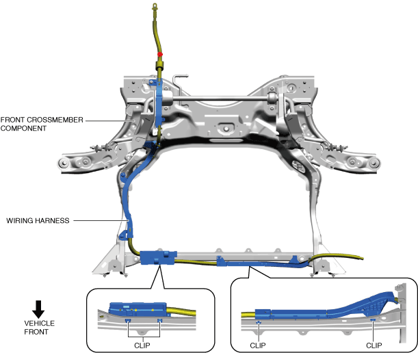
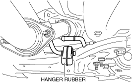
10. Disconnect the hanger rubber from the front crossmember and set it aside.
am3zzw00036468
|
11. Remove the joint cover. (See STEERING WHEEL AND COLUMN REMOVAL/INSTALLATION [(E)].)
12. Disconnect the intermediate shaft from the steering gear and linkage. (See STEERING WHEEL AND COLUMN REMOVAL/INSTALLATION [(E)].)
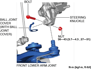
13. Disconnect the front lower arm ball joint from the steering knuckle. (See Front Lower Arm Ball Joint Installation Note.) (See Front Lower Arm Ball Joint Installation Note (With Ball Joint Cover).)
am3zzw00037038
|
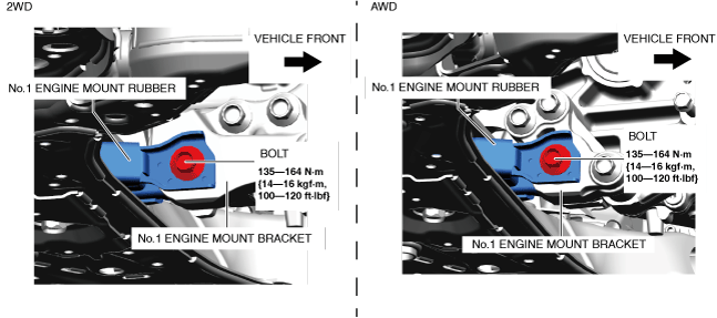
14. Remove the No.1 engine mount rubber installation bolt.
am3zzw00036465
|
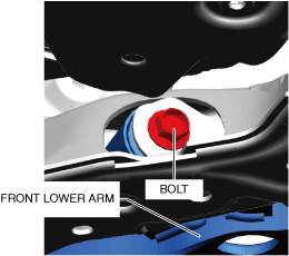
15. Lower the front crossmember component approx. 30 mm to the position where the front lower arm installation bolt can be removed.
am3zzw00036466
|
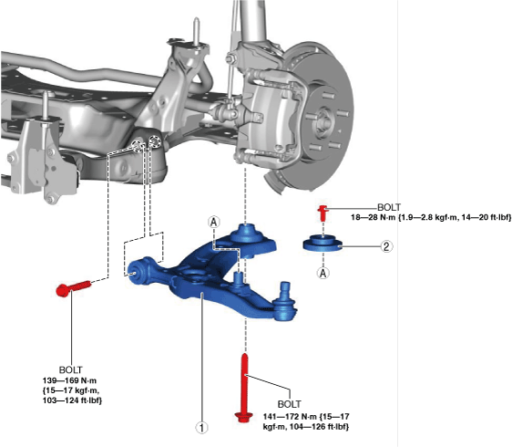
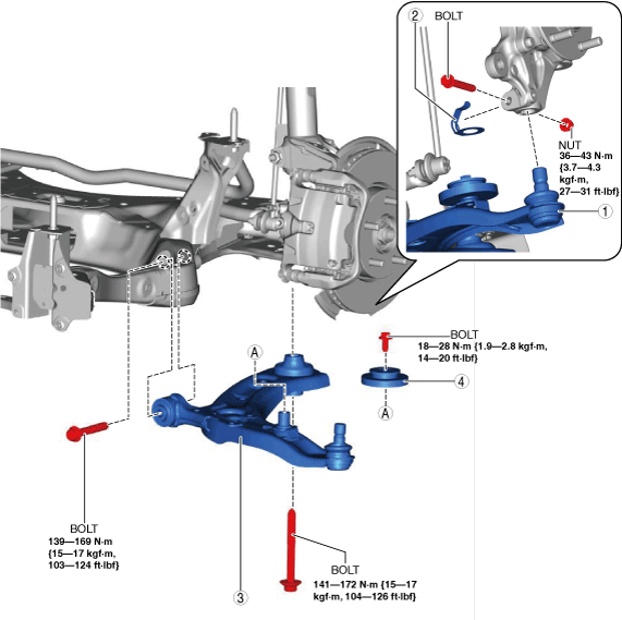
16. Remove in the order shown in the figure.
17. Install in the reverse order of removal. (See Suspension Links Installation Note.)
18. If the front lower arm component is replaced, inspect the wheel alignment and adjust it if necessary. (See FRONT WHEEL ALIGNMENT [(E)].)
am3zzw00036470
|
|
1
|
Front lower arm
|
|
2
|
Dynamic damper (with dynamic damper)
|
LH MTX(SKYACTIV-G 1.5 MTX/ATX), RH
1. Remove the wheel and tire. (See WHEEL AND TIRE REMOVAL/INSTALLATION.)
2. Remove the front under cover No.2. (See FRONT UNDER COVER No.2 REMOVAL/INSTALLATION.)
3. Remove in the order shown in the figure.
4. Install in the reverse order of removal. (See Suspension Links Installation Note.)
5. If the front lower arm component is replaced, inspect the wheel alignment and adjust it if necessary. (See FRONT WHEEL ALIGNMENT [(E)].)
am3zzw00036471
|
|
1
|
Front lower arm ball joint
|
|
2
|
Ball joint cover (with ball joint cover)
|
|
3
|
Front lower arm
|
|
4
|
Dynamic damper (with dynamic damper)
|
Suspension Links Installation Note
1. When installing the joint section with a rubber bushing, perform the following steps.
Front Lower Arm Ball Joint Installation Note
ac30zw00004031
|
1. Insert the bolt from the front of the vehicle and tighten the nut to the specified torque.
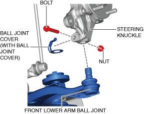
Front Lower Arm Ball Joint Installation Note (With Ball Joint Cover)
1. Install a ball joint cover to the steering knuckle before installing the front lower arm ball joint.
am3zzw00037039
|
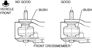
Front Lower Arm Installation Note (VIN: 3M*)
1. Verify that the inner bushing is correctly assembled to the front crossmember without any gaps before tightening the bolt shown in the figure.
am3zzw00031426
|
2. Install the front lower arm.