COUPLER COMPONENT REMOVAL/INSTALLATION [CW6A-EL]
id0517l1112400
Replacement Part
|
tie wrap clip
Quantity: 3
Location of use: Coupler component
|
-
Warning
-
• A hot transaxle and ATF can cause severe burns. Turn off the engine and wait until they are cool.
• Always wear protective eye wear when using the air compressor. If the air compressor is used, any particles of dirt or sludge could spatter and get into the eyes.
-
Caution
-
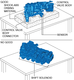
• If the control valve body is placed with the shift solenoid side facing down on a workbench, the wiring harness or connector of the coupler component may be damaged. When placing the control valve body on a workbench, always place it with the control valve body connector side facing down. However if the control valve body is directly placed on the workbench, the control valve body connector area or the sensor may be damaged. Always place the control valve body on an impact-absorbing material, which is free of foreign matter, so that the connector area and the sensor do not contact the workbench directly.
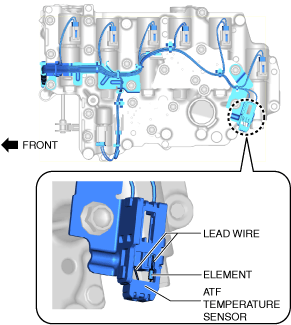
• Touching the ATF temperature sensor element or the lead wires by hand may cause a malfunction. When handling the coupler component, do not touch the ATF temperature sensor element or the lead wires.
• Do not apply excessive force to the coupler component wiring harness.
• Do not twist the coupler component wiring harness.
1. Select the selector lever to P position.
2. Disconnect the negative battery terminal. (See NEGATIVE BATTERY TERMINAL DISCONNECTION/CONNECTION [(E)].)
3. Remove the front under cover No.1. (See FRONT UNDER COVER No.1 REMOVAL/INSTALLATION.)
4. Remove the front under cover No.2. (See FRONT UNDER COVER No.2 REMOVAL/INSTALLATION.)
5. Clean the transaxle exterior throughout with a steam cleaner or cleaning solvents.
6. Remove the following parts as a single unit. (See INTAKE-AIR SYSTEM REMOVAL/INSTALLATION [SKYACTIV-G (WITHOUT CYLINDER DEACTIVATION (E))].)
-
• Air cleaner cover
• Air cleaner element
• Fresh-air duct
• Air cleaner case
• Air hose
• Resonance chamber
7. Drain the ATF. (See AUTOMATIC TRANSAXLE FLUID (ATF) REPLACEMENT [CW6A-EL].)
8. Remove the control valve body. (See CONTROL VALVE BODY REMOVAL/INSTALLATION [CW6A-EL].)
9. Remove the oil seal (control valve body). (See OIL SEAL (CONTROL VALVE BODY) REPLACEMENT [CW6A-EL].)
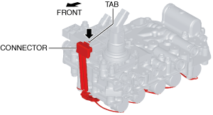
10. Release the tab shown in the figure and disconnect the connector.
-
Caution
-
• When disconnecting connectors, grasp the connectors, not the wiring harnesses. Otherwise, the wiring harnesses may be pulled out of the connector causing poor contact. Disconnect the connector by pulling the connector part straight with the connector tab released.
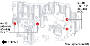
11. Loosen the bolts shown in the figure.
-
Note
-
• The connector can be disconnected easily by loosening the bolts.
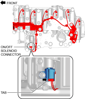
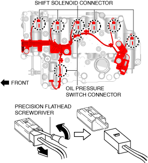
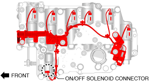
12. Release the ON/OFF solenoid connector tab using a finger and disconnect the ON/OFF solenoid connector.
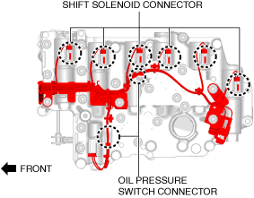
13. Insert a precision flathead screwdriver and move it in the direction of the arrow to disconnect shift solenoid connectors and oil pressure switch connectors.
-
Caution
-
• Do not scratch the shift solenoid, shift solenoid connector, oil pressure switch, and oil pressure switch connector with the precision flathead screwdriver.
• When disconnecting connectors, grasp the connectors, not the wiring harnesses. Otherwise, the wiring harnesses may be pulled out of the connector causing poor contact.
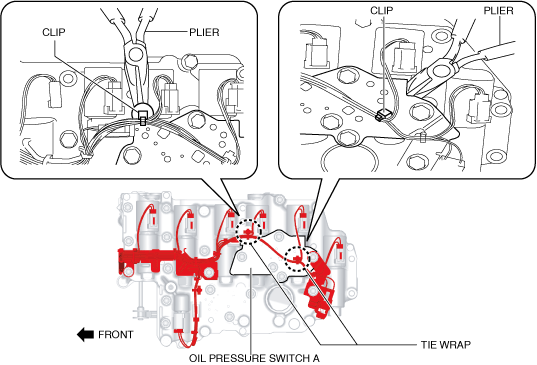
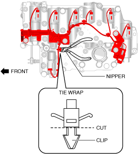
14. Using pliers, detach the tie wrap clips secured to oil pressure switch A.
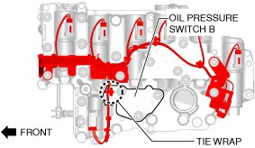
15. Using the following procedure, remove the tie wrap clip secured to the oil pressure switch B.
- (1) Using pliers, pull up the A part of the tie wrap.
-
- (2) Using nippers, cut the tie wrap clip.
-
-
Caution
-
• Collect and dispose of the cut tie wrap clip and its fragments securely.
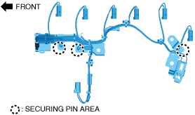
16. Remove the coupler component.
-
Caution
-
• The pins for securing the solenoid valves are located in the area circled with a dotted line, and they may drop down and be lost during coupler component removal. When removing the coupler component, be careful not to drop the pins for securing the solenoid valves, and if they do drop, be careful that they do not got lost.
17. Connect the oil pressure switch connectors and shift solenoid connectors.
-
Caution
-
• Insert the connector until a click is heard.
18. Connect the ON/OFF solenoid connector.
-
Caution
-
• Insert the connector until a click is heard.
19. Install the coupler component.
-
Caution
-
• When tightening the bolts, be careful not to pinch the coupler component wiring harness. If the wiring harness is pinched, replace the coupler component.
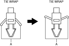
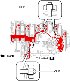
20. Assemble new tie wrap clips.
-
Caution
-
• Assemble the tie wrap clips in the direction shown in the figure.
• Verify that the tie wrap clips are assembled to the control valve body securely.
• Be careful not to let the coupler component wiring harness contact the surrounding parts.
• Do not twist the coupler component wiring harness.
21. Install the control valve body. (See CONTROL VALVE BODY REMOVAL/INSTALLATION [CW6A-EL].)
22. Install the oil seal (control valve body). (See OIL SEAL (CONTROL VALVE BODY) REPLACEMENT [CW6A-EL].)
23. Install the hose clamp. (See CONTROL VALVE BODY REMOVAL/INSTALLATION [CW6A-EL].)
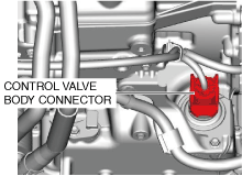
24. Connect the control valve body connector.
-
Caution
-
• Make sure that your hand does not touch the terminal as the connector terminal could be damaged.
• Verify that there is no fluid or foreign matter adhering to the connector before connecting the connector.
• Insert the connector straight as the connector terminal could be damaged.
• Rotate the connector lever until a click is heard.
25. Add the ATF. (See AUTOMATIC TRANSAXLE FLUID (ATF) REPLACEMENT [CW6A-EL].)
26. Install the following parts as a single unit. (See INTAKE-AIR SYSTEM REMOVAL/INSTALLATION [SKYACTIV-G (WITHOUT CYLINDER DEACTIVATION (E))].)
-
• Air cleaner cover
• Air cleaner element
• Fresh-air duct
• Air cleaner case
• Air hose
• Resonance chamber
27. Connect the negative battery terminal. (See NEGATIVE BATTERY TERMINAL DISCONNECTION/CONNECTION [(E)].)
28. Perform the “Mechanical System Test”. (See MECHANICAL SYSTEM TEST [CW6A-EL].)
29. Install the front under cover No.2. (See FRONT UNDER COVER No.2 REMOVAL/INSTALLATION.)
30. Install the front under cover No.1. (See FRONT UNDER COVER No.1 REMOVAL/INSTALLATION.)