 |
am3zzw00021700
SHIFT-LOCK SOLENOID INSPECTION
id051800298100
1. Disconnect the negative battery terminal. (See NEGATIVE BATTERY TERMINAL DISCONNECTION/CONNECTION [(E)].)
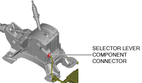
2. Remove the following parts:
3. Reconnect the negative battery terminal. (See NEGATIVE BATTERY TERMINAL DISCONNECTION/CONNECTION [(E)].)
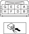
4. Verify that the voltages of each of the selector lever component terminals are as indicated in the table.
am3zzw00021700
|
am3zzw00034748
|
Standard
|
Terminal |
Connected to |
Test condition |
Voltage (V) |
|---|---|---|---|
|
A
|
IG1 relay No.2
|
Ignition switched ON (engine on)
|
B+
|
|
Except above
|
Below 1.0
|
||
|
E
|
Shift panel indicator
|
The following conditions are met (except emergency manual shift-lock release system is operated)
― Selector lever is in P position
― Ignition is switched to ON
― Brake pedal is depressed (brake light switch is on)
|
Below 1.0
|
|
Except above
|
B+
|