|
1
|
DETERMINE IF MALFUNCTION CAUSED BY A/C SYSTEM OPERATION
• Verify the A/C system operation.
• Is the A/C system operation normal?
|
Yes
|
Go to the next step.
|
|
No
|
Perform the symptom troubleshooting “A/C DOES NOT WORK SUFFICIENTLY” and “A/C IS ALWAYS ON OR A/C COMPRESSOR RUNS CONTINUOUSLY”.
|
|
2
|
DETERMINE IF MALFUNCTION CAUSED BY ATX BODY
• Compare the malfunction symptom with the i-stop system stop condition.
• Is there any shock or slippage during acceleration with the i-stop system disabled?
|
Yes
|
Perform the applicable symptom troubleshooting procedure.
|
|
No
|
Go to the next step.
|
|
3
|
VERIFY DTC
• Perform the DTC inspection for the following modules.
-
― PCM
― TCM
― DSC HU/CM
― SAS control module
• Are any DTCs displayed?
|
Yes
|
Repair the malfunctioning location according to the applicable DTC troubleshooting.
|
|
No
|
Go to the next step.
|
|
4
|
DETERMINE IF MALFUNCTION CAUSE IS BRAKE FLUID PRESSURE SENSOR SIGNAL OR OTHER
• Put the vehicle in an i-stop condition (engine stopped).
• Monitor the PCM PID BRK_FLD_PRES using the M-MDS while the brake is depressed and held with the i-stop function operating.
• Does the monitoring value change?
|
Yes
|
Refer to the controller area network (CAN) malfunction diagnosis flow to inspect for a CAN communication error.
• If the CAN communication is normal, repeat the inspection from Step 1.
-
― If the malfunction recurs, perform the following procedure.
-
• Replace the DSC HU/CM. (Brake fluid pressure sensor (built-into DSC HU/CM) or DSC HU/CM brake pressure hold function malfunction.)
― Perform the repair completion verification 1.
|
|
No
|
Go to the next step.
|
|
5
|
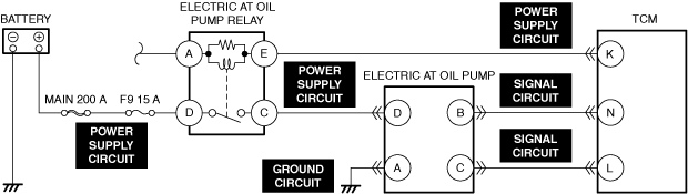
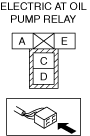
INSPECT ELECTRIC AT OIL PUMP RELAY FOR MALFUNCTION
• Inspect the applicable part.
• Is the part normal?
|
Yes
|
Go to the next step.
|
|
No
|
Repair or replace the malfunctioning location and perform the repair completion verification 1.
|
|
6
|
INSPECT ELECTRIC AT OIL PUMP RELAY POWER SUPPLY CIRCUIT FOR SHORT TO GROUND OR OPEN CIRCUIT
• Inspect the applicable circuit for an open circuit and short to ground.
• Is the circuit normal?
|
Yes
|
Go to the next step.
|
|
No
|
Repair or replace the malfunctioning location and perform the repair completion verification 1.
|
|
7
|
INSPECT ELECTRIC AT OIL PUMP CONNECTOR FOR MALFUNCTION
• Inspect the applicable connector and terminal.
• Are the connector and terminal normal?
|
Yes
|
Go to the next step.
|
|
No
|
Repair or replace the malfunctioning location and perform the repair completion verification 1.
|
|
8
|
INSPECT ELECTRIC AT OIL PUMP GROUND CIRCUIT FOR OPEN CIRCUIT
• Inspect the applicable circuit for an open circuit.
• Is the circuit normal?
|
Yes
|
Go to the next step.
|
|
No
|
Repair or replace the malfunctioning location and perform the repair completion verification 1.
|
|
9
|
INSPECT ELECTRIC AT OIL PUMP POWER SUPPLY CIRCUIT FOR SHORT TO GROUND
• Inspect the applicable circuit for a short to ground.
• Is the circuit normal?
|
Yes
|
Go to the next step.
|
|
No
|
Repair or replace the malfunctioning location and perform the repair completion verification 1.
|
|
10
|
INSPECT ELECTRIC AT OIL PUMP POWER SUPPLY CIRCUIT FOR OPEN CIRCUIT
• Inspect the applicable circuit for an open circuit.
• Is the circuit normal?
|
Yes
|
Go to the next step.
|
|
No
|
Repair or replace the malfunctioning location and perform the repair completion verification 1.
|
|
11
|
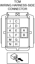
INSPECT TCM CONNECTOR FOR MALFUNCTION
• Inspect the applicable connector and terminal.
• Are the connector and terminal normal?
|
Yes
|
Go to the next step.
|
|
No
|
Repair or replace the malfunctioning location and perform the repair completion verification 1.
|
|
12
|
INSPECT TCM POWER SUPPLY CIRCUIT AND SIGNAL CIRCUIT FOR SHORT TO GROUND
• Inspect the applicable circuit for a short to ground.
• Is the circuit normal?
|
Yes
|
Go to the next step.
|
|
No
|
Repair or replace the malfunctioning location and perform the repair completion verification 1.
|
|
13
|
INSPECT TCM POWER SUPPLY CIRCUIT AND SIGNAL CIRCUIT FOR OPEN CIRCUIT
• Inspect the applicable circuit for an open circuit.
• Is the circuit normal?
|
Yes
|
Refer to the controller area network (CAN) malfunction diagnosis flow to inspect for a CAN communication error.
• If the CAN communication is normal, perform the diagnosis from Step 1.
-
― If the malfunction recurs, replace the electric AT oil pump and perform the repair completion verification 1.
|
|
No
|
Repair or replace the malfunctioning location and perform the repair completion verification 1.
|
|
14
|
INSPECT RELATED PART CONDITION
• Inspect the following:
-
― Lack of ATF
― Brake dragging
• Are all items normal?
|
Yes
|
Go to the next step.
|
|
No
|
Repair or replace the malfunctioning location and perform the repair completion verification 1.
|
|
15
|
INSPECT DRIVE BELT FOR MALFUNCTION
• Inspect the applicable part.
• Is the part normal?
|
Yes
|
Go to the next step.
|
|
No
|
Repair or replace the malfunctioning location and perform the repair completion verification 1.
|
|
16
|
INSPECT FOR FUEL LEAKAGE FROM FUEL SYSTEM
• Visually inspect the following:
-
― Fuel leakage from the fuel tank, fuel pump, hose, pipe, fuel injector, supply pump, common rail
― Cracking and damage in fuel hose and pipe
― Clamp installation condition for each hose and pipe
― Fuel pipe securing condition due to deterioration such as rubber of clamp
• Are all items normal?
|
Yes
|
Go to the next step.
|
|
No
|
Repair or replace the malfunctioning location and perform the repair completion verification 1.
|
|
17
|
INSPECT FUEL INJECTION SYSTEM RELATED PARTS
• Inspect the following parts:
-
― Fuel pressure relief valve
• Are all items normal?
|
Yes
|
Go to the next step.
|
|
No
|
Repair or replace the malfunctioning location and perform the repair completion verification 1.
|
|
18
|
INSPECT FOR MALFUNCTION DUE TO POOR FUEL
• Does the symptom disappear?
|
Yes
|
Advise the customer as to the change in the fuel used.
|
|
No
|
Remove the accumulated matter in the cylinder head using the following procedure, then go to the next step.
• Carbon remover
• Overhauling
|
|
19
|
DETERMINE IF MALFUNCTION IS DUE TO EXCESSIVE ENGINE SPEED RESISTANCE
• Rotate the crankshaft pulley lock bolt clockwise using a wrench.
• Can the bolt be rotated?
|
Yes
|
Go to Step 21.
|
|
No
|
Go to the next step.
|
|
20
|
INSPECT FOR MALFUNCTION DUE TO EXCESSIVE MECHANICAL RESISTANCE OF ENGINE ACCESSORIES
• Remove all drive belts from engine accessories.
-
Caution
-
• Do not run the engine with the drive belts of engine accessories removed. Otherwise the engine could be damaged from overheating.
• Start the engine.
• Is cranking possible? (Does engine start?)
|
Yes
|
Mechanical resistance in engine accessories.
• Repair or replace the malfunctioning location and perform the repair completion verification 1.
|
|
No
|
Go to the next step.
|
|
21
|
INSPECT ENGINE COMPRESSION
• Inspect the engine compression.
• Are compression pressures within specification?
|
Yes
|
Perform the repair completion verification 1.
|
|
No
|
Go to the next step.
|
|
22
|
INSPECT FOR MALFUNCTION DUE TO DEVIATED VALVE TIMING
• Inspect the valve timing (timing chain installation condition).
• Is the valve timing normal?
|
Yes
|
Go to the next step.
|
|
No
|
Adjust the valve timing to the correct timing and perform the repair completion verification 1.
|
|
23
|
INSPECT FOR MALFUNCTION DUE TO INTERNAL ENGINE WEAR, DAMAGE
• Inspect for the following engine internal parts:
-
― Cylinder
― Piston ring
― Intake valve
― Exhaust valve
― Such as cylinder head gasket
• Are all items normal?
|
Yes
|
Refer to the controller area network (CAN) malfunction diagnosis flow to inspect for a CAN communication error.
• If the CAN communication is normal, perform the diagnosis from Step 1.
-
― If the malfunction recurs, replace the lower case, then perform the repair completion verification 1. (Fuel may not inject normally.)
|
|
No
|
Repair or replace the malfunctioning location and perform the repair completion verification 1.
|
|
Repair completion verification 1
|
VERIFY THAT VEHICLE IS REPAIRED
• Install/connect the part removed/disconnected during the troubleshooting procedure.
• Has the malfunction symptom been eliminated?
|
Yes
|
Complete the symptom troubleshooting. (Explain contents of repair to customer)
|
|
No
|
Refer to the controller area network (CAN) malfunction diagnosis flow to inspect for a CAN communication error.
• If the CAN communication is normal, perform the diagnosis from Step 1.
-
― If the malfunction recurs, go to the next step.
|
|
Repair completion verification 2
|
VERIFY IF MALFUNCTION IS CAUSED BY NOT PERFORMING PCM REPROGRAMMING
• Verify repair information and verify that there is a new calibration in the PCM.
• Is there a new calibration in the PCM?
|
Yes
|
Perform the PCM reprogramming and verify if the malfunction symptom was corrected.
• If the malfunction recurs, replace the PCM.
|
|
No
|
Replace the PCM.
|