 |
am6xuw00002472
VARIABLE VALVE TIMING ACTUATOR INSPECTION [L3 Turbo]
id0110b3801200
1. Remove the battery cover. (See BATTERY REMOVAL/INSTALLATION [L3 Turbo].)
2. Disconnect the negative battery cable.
3. Remove the charge air cooler. (See INTAKE-AIR SYSTEM REMOVAL/INSTALLATION [L3 Turbo].)
4. Remove the ignition coils. (See IGNITION COIL REMOVAL/INSTALLATION [L3 Turbo].)
5. Disconnect the ventilation hose from the cylinder head cover. (See QUICK RELEASE CONNECTOR (EMISSION SYSTEM) REMOVAL/INSTALLATION [L3 Turbo].)
6. Remove the cylinder head cover. (See TIMING CHAIN REMOVAL/INSTALLATION [L3 Turbo].)
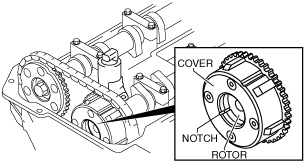
7. Confirm that notch of the rotor and notch of the cover at the variable valve timing actuator are aligned and fitted.
am6xuw00002472
|
8. Install the cylinder head cover. (See TIMING CHAIN REMOVAL/INSTALLATION [L3 Turbo].)
9. Connect the ventilation hose. (See QUICK RELEASE CONNECTOR (EMISSION SYSTEM) REMOVAL/INSTALLATION [L3 Turbo].)
10. Install the ignition coils. (See IGNITION COIL REMOVAL/INSTALLATION [L3 Turbo].)
11. Install the charge air cooler. (See INTAKE-AIR SYSTEM REMOVAL/INSTALLATION [L3 Turbo].)
12. Connect the negative battery cable.
13. Install the battery cover. (See BATTERY REMOVAL/INSTALLATION [L3 Turbo].)