am3uuw00005068
|
COMBINED SENSOR REMOVAL/INSTALLATION
id041500801200
1. Perform the following procedures:
am3uuw00005068
|
2. Partially peel back the floor covering.
3. Remove in the order indicated in the table.
4. Install in the reverse order of removal.
5. After installation, perform the combined sensor initialization procedure. (See DSC SENSOR INITIALIZATION PROCEDURE.)
am3uuw00002732
|
|
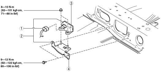
1
|
Combined sensor connector
|
|
2
|
Combined sensor, bracket
|
|
3
|
Combined sensor
|
|
4
|
Bracket
|