 |
am3zzw00005487
CLUTCH UNIT REMOVAL/INSTALLATION [F35M-R]
id0510008003m0
1. Remove the battery cover. (See BATTERY REMOVAL/INSTALLATION [ZY, Z6].)
2. Disconnect the negative battery cable. (See BATTERY REMOVAL/INSTALLATION [ZY, Z6].)
3. Remove the following parts:
4. Drain the transaxle oil into a suitable container. (See TRANSAXLE OIL REPLACEMENT [F35M-R].)
5. Remove the manual transaxle. (See MANUAL TRANSAXLE REMOVAL/INSTALLATION [F35M-R].)
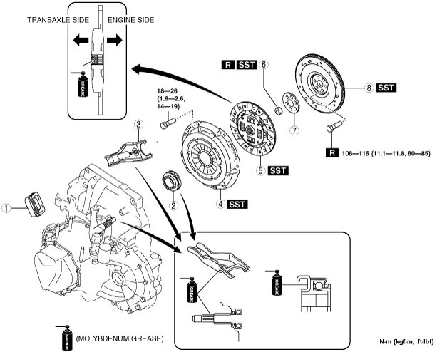
6. Remove in the order indicated in the table.
7. Install in the reverse order removal.
8. Add the specified amount of specified transaxle oil. (See TRANSAXLE OIL REPLACEMENT [F35M-R].)
am3zzw00005487
|
|
1
|
Boot
|
|
2
|
Clutch release collar
|
|
3
|
Clutch release fork
|
|
4
|
Clutch cover
|
|
5
|
Clutch disc
|
|
6
|
Pilot bearing
(See Pilot Bearing Removal Note.)
|
|
7
|
Plate
|
|
8
|
Flywheel
(See Flywheel Removal Note.)
(See Flywheel Installation Note.)
|
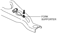
Clutch Release Fork Removal Note
1. Remove the fork supporter before disassembling the clutch release fork.
am3uuw00002080
|
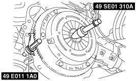
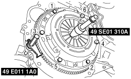
Clutch Cover and Disc Removal Note
1. Install the SSTs.
am3zzw00005488
|
2. Loosen each bolt one turn at a time in a crisscross pattern until spring tension is released.
3. Remove the clutch cover and disc.
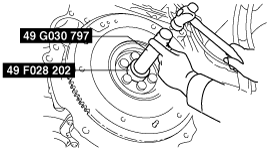
Pilot Bearing Removal Note
1. Use the SST to remove the pilot bearing.
am3zzw00005489
|
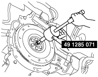
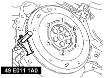
Flywheel Removal Note
1. Hold the flywheel using the SST.
am3zzw00005490
|
2. Remove the bolts evenly and gradually in a crisscross pattern.
3. Remove the flywheel.
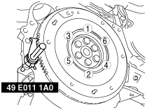
Flywheel Installation Note
1. Clean the crankshaft thread holes.
2. Install the flywheel to the crankshaft.
3. Hand‐tighten the new flywheel lock bolts.
4. Install the SST to the flywheel.
am3zzw00005491
|
5. Gradually tighten the flywheel lock bolts in a crisscross pattern.
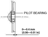
Pilot Bearing Installation Note
1. Use the SSTs to install the pilot bearing.
am3zzw00005492
|
2. As shown in the figure, press-fit the pilot bearing to the position which is 0—0.4 mm {0.00—0.01 in} from the crankshaft end.
am3zzw00008192
|
Clutch Disc Installation Note
1. Clean the splines of the clutch disc and the main drive gear with a brush.
2. Spread a thin layer of clutch grease on the splines.
3. Hold the clutch disc position using the SST.
am3zzw00008193
|
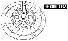
Clutch Cover Installation Note
1. Install the SSTs.
am3zzw00005912
|
2. Tighten the bolts in Min. 2 stages.
3. Tighten partially with a crisscross pattern.
4. Fully tighten to specified torque with a crisscross pattern.