 |
am3zzw00008196
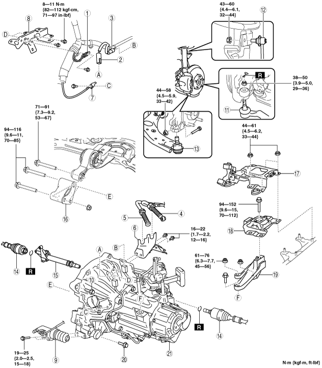
MANUAL TRANSAXLE REMOVAL/INSTALLATION [G66M-R (MZR 2.0 DISI i-stop)]
id0515k18006k5
1. Remove the battery cover. (See BATTERY REMOVAL/INSTALLATION [MZR 2.0 DISI i-stop].)
2. Disconnect the negative battery cable. (See BATTERY REMOVAL/INSTALLATION [MZR 2.0 DISI i-stop].)
3. Remove the battery and battery tray. (MZR 2.0 DISI i-stop)(See BATTERY REMOVAL/INSTALLATION [MZR 2.0 DISI i-stop].)
4. Remove the air cleaner component. (See INTAKE-AIR SYSTEM REMOVAL/INSTALLATION [MZR 2.0 DISI i-stop].)
5. Remove the exhaust manifold insulator installation bolts and set the exhaust manifold insulator aside. (See EXHAUST SYSTEM REMOVAL/INSTALLATION [MZR 2.0 DISI i-stop].)
6. Remove the following parts:
7. Drain the transaxle oil into a suitable container. (See TRANSAXLE OIL REPLACEMENT [G66M-R].)
8. Remove in the order indicated in the table.
9. Install in the reverse order of removal.
10. Add the specified amount of specified transaxle oil. (See TRANSAXLE OIL REPLACEMENT [G66M-R].)
am3zzw00008196
|
|
1
|
Ground
|
|
2
|
Back-up light switch connector
|
|
3
|
Neutral switch connector
|
|
4
|
Select cable
|
|
5
|
Shift cable
|
|
6
|
Cable bracket
|
|
7
|
Ground
|
|
8
|
Harness bracket
|
|
9
|
Clutch release cylinder
|
|
10
|
Transaxle mounting bolt (upper side)
|
|
11
|
Tie-rod end ball joint
|
|
12
|
Stabilizer control link
|
|
13
|
Lower arm ball joint
|
|
14
|
Drive shaft
|
|
15
|
Joint shaft
|
|
16
|
No.1 engine mount bracket
|
|
17
|
Battery tray bracket
|
|
18
|
No.4 engine mount rubber
|
|
19
|
No.4 engine mount bracket
|
|
20
|
Transaxle mounting bolt (lower side)
|
|
21
|
Manual transaxle
|
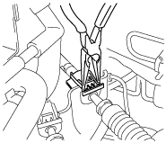
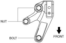
Shift Cable and Select Cable Removal Note
1. Remove the shift and selector cable outer ends as shown in the figure.
am3uuw00002130
|
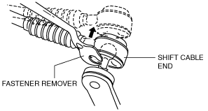
2. Remove the both shift cable end and select cable end using a fastener remover.
am3uuw00003309
|
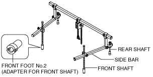
No.4 Engine Mount Removal Note
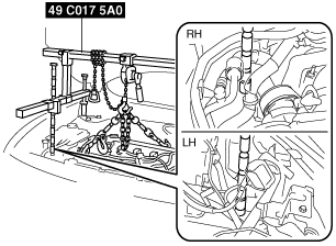
1. Install the SST using the following procedure.
am6xuw00001516
|
am3uuw00002131
|
am3uuw00002132
|
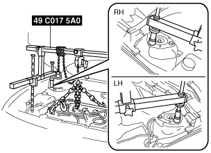
2. Support the engine using the SST.
am3uuw00002133
|
3. Remove the No.4 engine mount rubber and bracket.
Manual Transaxle Removal Note
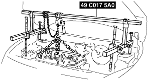
1. Adjust the SST and lean the engine toward the transaxle.
am3uuw00002133
|
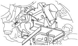
2. Support the transaxle on a jack.
am6xuw00001507
|
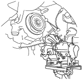
3. Remove the transaxle mounting bolts.
4. Remove the transaxle.
Manual Transaxle Installation Note
1. Set the transaxle on a jack and lift into place.
am6xuw00001508
|
2. Install the transaxle mounting bolts.
3. Adjust the SST (49 C017 5A0) so that the engine is located at the specified position.
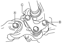
No.1 Engine Mount and No.4 Engine Mount Installation Note
1. Install the No.4 engine mount bracket on the transaxle case and tighten bolt and nuts.
am3uuw00005256
|
2. Install the through bolt A on the front crossmember side until approximately three pitches are showing.
3. Temporarily tighten bolts B.
4. Tighten the bolts in the order of B and C.
am3zzw00008202
|
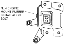
5. Tighten the No.4 engine mount rubber installation bolt as shown in the figure.
am3zzw00007640
|
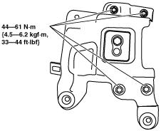
6. Tighten the No.1 engine mount rubber installation bolts as shown in the figure.
am3zzw00008203
|
|
No. |
Tightening torque |
|---|---|
|
1
|
71—91 N·m {7.3—9.2 kgf·m, 53—67 ft·lbf}
|
|
2
|
73—90 N·m {7.5—9.1 kgf·m, 54—66 ft·lbf}
|
7. Tighten the No.4 engine mount rubber and battery bracket bolts and nuts in the order as shown in the figure.
am3zzw00007641
|
8. Remove the SST (49 C017 5A0).