SOLENOID VALVE INSPECTION [FS5A-EL]
id051721293100
-
Caution
-
• Water or foreign objects entering the connector can cause a poor connection or corrosion. Be sure not to drop water or foreign objects on the connector when disconnecting it.
Primary Control Valve Body
On-vehicle inspection
1. Perform the following procedures.
- (1) Remove the battery cover. (See BATTERY REMOVAL/INSTALLATION [LF, L5].) (See BATTERY REMOVAL/INSTALLATION [MZR 2.0 DISI i-stop].)
- (2) Disconnect the negative battery cable.
- (3) Remove the air cleaner component. (See INTAKE-AIR SYSTEM REMOVAL/INSTALLATION [LF, L5].) (See INTAKE-AIR SYSTEM REMOVAL/INSTALLATION [MZR 2.0 DISI i-stop].)
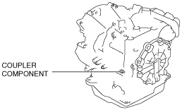
- (4) Disconnect the coupler component connector.
-
2. Measure the resistance between the coupler component terminals.
-
• If there is any malfunction, inspect the coupler component for continuity.
• If coupler component has no malfunction, perform the “Off-vehicle inspection“. (See
Off-Vehicle inspection.)
Solenoid valve specification
|
Solenoid valve
|
Terminal
|
Resistance (ohm)
|
|
Pressure control solenoid A
|
D↔I
|
2.4—7.3
|
|
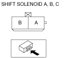
Shift solenoid A
|
A↔GND
|
1.0—4.2
|
|
Shift solenoid B
|
C↔GND
|
1.0—4.2
|
|
Shift solenoid C
|
G↔GND
|
1.0—4.2
|
|
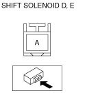
Shift solenoid D
|
B↔GND
|
10.9—26.2
|
|
Shift solenoid E
|
F↔GND
|
10.9—26.2
|
Operating inspection
-
Caution
-
• Do not apply battery position voltage to terminals for more than 3 s.
-
Note
-
• Because the operation sound of the solenoid valve is small, perform inspection in a quiet place.
1. Perform the following procedures.
- (1) Remove the battery cover. (See BATTERY REMOVAL/INSTALLATION [LF, L5].) (See BATTERY REMOVAL/INSTALLATION [MZR 2.0 DISI i-stop].)
- (2) Disconnect the negative battery cable.
- (3) Remove the air cleaner component. (See INTAKE-AIR SYSTEM REMOVAL/INSTALLATION [LF, L5].) (See INTAKE-AIR SYSTEM REMOVAL/INSTALLATION [MZR 2.0 DISI i-stop].)
- (4) Disconnect the coupler component connector.
-
2. Apply battery positive voltage to the coupler component terminals A, B, C, F or G and battery negative voltage to GND, and verify that operating sound is heard from solenoid valve.
-
• If the operation sound is not heard, inspect the coupler component for continuity.
• If coupler component has no malfunction, perform the “Off-vehicle inspection“. (See
Off-Vehicle inspection.)
3. Apply battery positive voltage to the coupler component terminal D and battery negative voltage to terminal I, and verify that operating sound is heard from solenoid valve.
-
• If the operation sound is not heard, inspect the coupler component for continuity.
• If coupler component has no malfunction, perform the “Off-vehicle inspection“. (See
Off-Vehicle inspection.)
Off-Vehicle inspection
1. Measure the resistance between the solenoid valve terminals.
-
-
Pressure control solenoid A specification
-
2.4—7.3 ohms
-
Shift solenoid A, B, C specification
-
1.0—4.2 ohms
-
Shift solenoid D, E specification
-
10.9—26.2 ohms
Secondary Control Valve Body
On-vehicle inspection
1. Perform the following procedures.
- (1) Remove the battery cover. (See BATTERY REMOVAL/INSTALLATION [LF, L5].) (See BATTERY REMOVAL/INSTALLATION [MZR 2.0 DISI i-stop].)
- (2) Disconnect the negative battery cable.
- (3) Remove the battery . (See BATTERY REMOVAL/INSTALLATION [LF, L5].) (See BATTERY REMOVAL/INSTALLATION [MZR 2.0 DISI i-stop].)
- (4) Remove the battery box. (See BATTERY REMOVAL/INSTALLATION [LF, L5].) (See BATTERY REMOVAL/INSTALLATION [MZR 2.0 DISI i-stop].)
- (5) Remove the battery tray. (See BATTERY REMOVAL/INSTALLATION [LF, L5].) (See BATTERY REMOVAL/INSTALLATION [MZR 2.0 DISI i-stop].)
- (6) Disconnect the coupler component connector.
-
2. Measure the resistance between the coupler component terminals A and B.
-
• If there is any malfunction, inspect the coupler component for continuity.
• If coupler component has no malfunction, perform the “Off-vehicle inspection“. (See
Off-Vehicle inspection.)
Solenoid valve specification
|
Solenoid valve
|
Terminal
|
Resistance (ohm)
|
|
Pressure control solenoid B
|
A↔GND
|
1.0—4.2
|
|
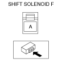
Shift solenoid F
|
B↔GND
|
8.4—21.8
|
Operating inspection
-
Caution
-
• Do not apply battery position voltage to terminals for more than 3 s.
-
Note
-
• Because the operation sound of the solenoid valve is small, perform inspection in a quiet place.
1. Perform the following procedures.
- (1) Remove the battery cover. (See BATTERY REMOVAL/INSTALLATION [LF, L5].) (See BATTERY REMOVAL/INSTALLATION [MZR 2.0 DISI i-stop].)
- (2) Disconnect the negative battery cable.
- (3) Remove the battery . (See BATTERY REMOVAL/INSTALLATION [LF, L5].) (See BATTERY REMOVAL/INSTALLATION [MZR 2.0 DISI i-stop].)
- (4) Remove the battery box. (See BATTERY REMOVAL/INSTALLATION [LF, L5].) (See BATTERY REMOVAL/INSTALLATION [MZR 2.0 DISI i-stop].)
- (5) Remove the battery tray. (See BATTERY REMOVAL/INSTALLATION [LF, L5].) (See BATTERY REMOVAL/INSTALLATION [MZR 2.0 DISI i-stop].)
- (6) Disconnect the coupler component connector.
-
2. Apply battery positive voltage to the coupler component terminals A, B and battery negative voltage to GND, and verify that operating sound is heard from solenoid valve.
-
• If the operation sound is not heard, inspect the coupler component for continuity.
• If coupler component has no malfunction, perform the “Off-vehicle inspection“. (See
Off-Vehicle inspection.)
Off-Vehicle inspection
1. Measure the resistance between the solenoid valve terminals.
-
-
Pressure control solenoid B specification
-
1.0—4.2 ohms
-
Shift solenoid F specification
-
8.4—21.8 ohms