 |
am3uuw00004480
OIL COOLER REMOVAL/INSTALLATION [FS5A-EL]
id051721294400
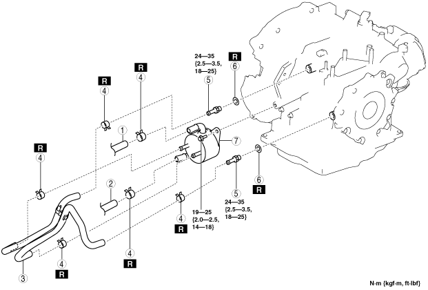
Type A
1. Remove the battery cover. (See BATTERY REMOVAL/INSTALLATION [LF, L5].)
2. Disconnect the negative battery cable.
3. Remove the air cleaner component. (See INTAKE-AIR SYSTEM REMOVAL/INSTALLATION [LF, L5].)
4. Remove the aerodynamic under cover No.2. (See AERODYNAMIC UNDER COVER NO.2 REMOVAL/INSTALLATION.)
5. Drain the ATF. (See AUTOMATIC TRANSAXLE FLUID (ATF) REPLACEMENT [FS5A-EL].)
6. Drain the engine coolant. (See ENGINE COOLANT REPLACEMENT [LF, L5].)
7. Remove in the order indicated in the table.
am3uuw00004480
|
|
1
|
Water hose (connected to the outlet)
|
|
2
|
Water hose (connected to the thermostat)
|
|
3
|
Oil hose
(See Oil Hose Installation Note.)
|
|
4
|
Hose clamp
|
|
5
|
Connector bolt
|
|
6
|
Packing
|
|
7
|
Water-cooled oil cooler
|
8. Install in the reverse order of removal.
9. Add the engine coolant. (See ENGINE COOLANT REPLACEMENT [LF, L5].)
10. Add the ATF. (See AUTOMATIC TRANSAXLE FLUID (ATF) REPLACEMENT [FS5A-EL].)
11. Perform the “Mechanical System Test”. (See MECHANICAL SYSTEM TEST [FS5A-EL].)
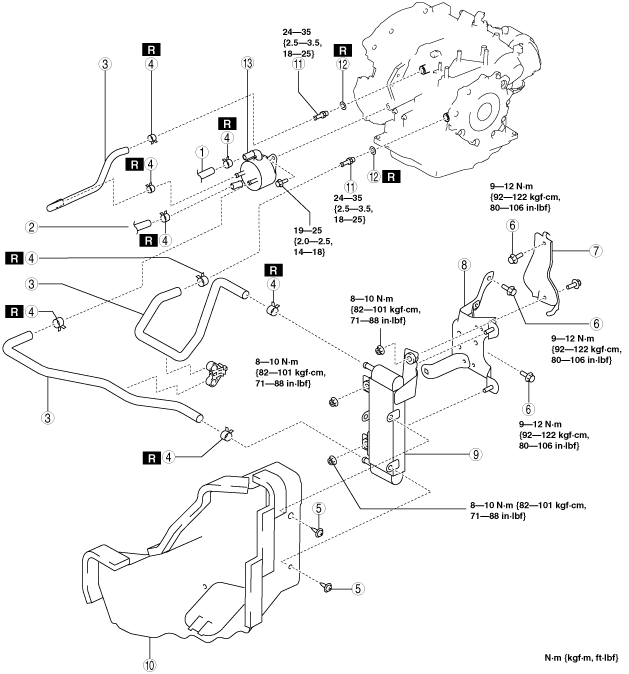
Type B
1. Remove the battery cover. (See BATTERY REMOVAL/INSTALLATION [LF, L5].)
2. Disconnect the negative battery cable.
3. Remove the air cleaner component. (See INTAKE-AIR SYSTEM REMOVAL/INSTALLATION [LF, L5].)
4. Remove the aerodynamic under cover No.2. (See AERODYNAMIC UNDER COVER NO.2 REMOVAL/INSTALLATION.)
5. Remove the front splash shield (LH). (See SPLASH SHIELD REMOVAL/INSTALLATION.)
6. Remove the front mudguard (LH). (See FRONT MUDGUARD REMOVAL/INSTALLATION.)
7. Drain the ATF. (See AUTOMATIC TRANSAXLE FLUID (ATF) REPLACEMENT [FS5A-EL].)
8. Drain the engine coolant. (See ENGINE COOLANT REPLACEMENT [LF, L5].)
9. Remove in the order indicated in the table.
am3zzw00006971
|
|
1
|
Water hose (connected to the heater outlet)
|
|
2
|
Water hose (connected to the thermostat)
|
|
3
|
Oil hose
(See Oil Hose Installation Note.)
|
|
4
|
Hose clamp
(See Oil Hose Installation Note.)
|
|
5
|
Fastener
|
|
6
|
Bracket installation bolt
|
|
7
|
Bracket
|
|
8
|
Bracket
|
|
9
|
Air-cooled oil cooler
|
|
10
|
Oil cooler duct
|
|
11
|
Connector bolt
|
|
12
|
Packing
|
|
13
|
Water-cooled oil cooler
|
10. Install in the reverse order of removal.
11. Add the engine coolant. (See ENGINE COOLANT REPLACEMENT [LF, L5].)
12. Add the ATF. (See AUTOMATIC TRANSAXLE FLUID (ATF) REPLACEMENT [FS5A-EL].)
13. Perform the “Mechanical System Test”. (See MECHANICAL SYSTEM TEST [FS5A-EL].)
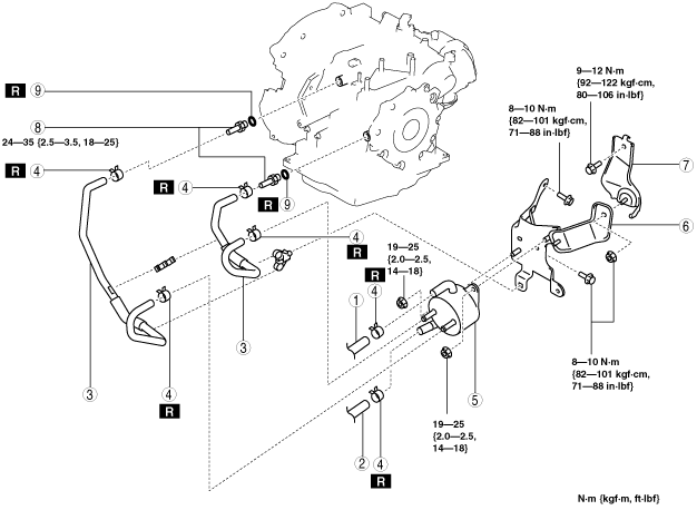
Type C
1. Remove the battery cover. (See BATTERY REMOVAL/INSTALLATION [MZR 2.0 DISI i-stop].)
2. Disconnect the negative battery cable.
3. Remove the air cleaner component. (See INTAKE-AIR SYSTEM REMOVAL/INSTALLATION [MZR 2.0 DISI i-stop].)
4. Remove the aerodynamic under cover No.2. (See AERODYNAMIC UNDER COVER NO.2 REMOVAL/INSTALLATION.)
5. Remove the front splash shield (LH). (See SPLASH SHIELD REMOVAL/INSTALLATION.)
6. Remove the front mudguard (LH). (See FRONT MUDGUARD REMOVAL/INSTALLATION.)
7. Drain the ATF. (See AUTOMATIC TRANSAXLE FLUID (ATF) REPLACEMENT [FS5A-EL].)
8. Drain the engine coolant. (See ENGINE COOLANT REPLACEMENT [MZR 2.0 DISI i-stop].)
9. Remove in the order indicated in the table.
am3zzw00009922
|
|
1
|
Water hose (connected to the heater outlet)
|
|
2
|
Water hose (connected to the thermostat)
|
|
3
|
Oil hose
(See Oil Hose Installation Note.)
|
|
4
|
Hose clamp
(See Oil Hose Installation Note.)
|
|
5
|
Water-cooled oil cooler
|
|
6
|
Bracket
|
|
7
|
Bracket
|
|
8
|
Connector bolt
|
|
9
|
Packing
|
10. Install in the reverse order of removal.
11. Add the engine coolant. (See ENGINE COOLANT REPLACEMENT [MZR 2.0 DISI i-stop].)
12. Add the ATF. (See AUTOMATIC TRANSAXLE FLUID (ATF) REPLACEMENT [FS5A-EL].)
13. Perform the “Mechanical System Test”. (See MECHANICAL SYSTEM TEST [FS5A-EL].)
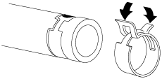
Oil Hose Installation Note
1. Align the marks, and slide the oil hose onto the oil pipe until it is fully seated as shown.
am6xuw00001957
|
2. Install the hose clamp.
3. Install the hose clamp onto the hose.
ampjjw00005653
|
4. Verify that the hose clamp does not interfere with any other components.