ELECTRIC AT OIL PUMP INSPECTION [FS5A-EL]
id051721335400
-
Caution
-
• Do not drop or apply a shock to the electric AT oil pump. Replace the electric AT oil pump if it has been dropped or received an impact.
• Do not disassemble the electric AT oil pump. Replace the electric AT oil pump if it has been disassembled.
1. Make preparations to perform the hydraulic pressure measurement.
- (1) Remove the aerodynamic under cover No.2. (See AERODYNAMIC UNDER COVER NO.2 REMOVAL/INSTALLATION.)
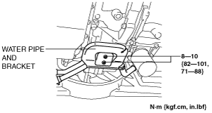
- (2) Disconnect the water pipe and bracket from the electric AT oil pump bracket and set it out of the way.
-
- (3) Disconnect the electric AT oil pump from the ATX. (See ELECTRIC AT OIL PUMP REMOVAL/INSTALLATION [FS5A-EL].)
-
-
Note
-
• Do not disconnect the oil hose and connector connected to the electric AT oil pump and ATX.
- (4) Remove the electric AT oil pump bracket. (See ELECTRIC AT OIL PUMP REMOVAL/INSTALLATION [FS5A-EL].)
- (5) Secure the disconnected electric AT oil pump and water pipe and bracket to a place out of the way using rope.
-
-
Caution
-
• To prevent damage to the parts, be careful not to perform the following:
-
― Do not pull the wiring harness, oil hose, and water hose excessively.
― Do not twist the oil hose and water hose.
― Do not allow parts to interfere with the cooling fan.
- (6) Remove the square-head plug from the line pressure inspection port.
-
-
Warning
-
• Removing the square-head plug when the ATF is hot can be dangerous. Hot ATF can come out of the opening and badly burn you. Before removing the square-head plug, allow the ATF to cool.
- (7) Connect the SSTs as following:
-
-
• When using the oil pressure gauge set (49 0378 400C), connect the SSTs (49 H019 002, 49 0378 400C, 49 B019 901B) to the line pressure inspection port as shown in the figure.
• When using the oil pressure gauge set (49 D019 9A2), connect the SSTs (49 D019 910, 49 D019 911, 49 D019 913, 49 D019 909, 49 D019 908) to the line pressure inspection port as shown in the figure.
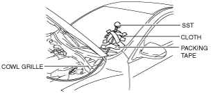
- (8) Route the SST hose (49 0378 400C or 49 D019 909) so that it does not interfere with the cooling fan, and secure it to the air cleaner with packing tape.
-
- (9) While the bonnet is closed, install the SST hose (49 0378 400C or 49 D019 909) so that it does not get caught in between the bonnet and cowl grille.
- (10) Protect the SST with a clean cloth and secure it to the windshield using packing tape so that the needle of the SST oil pressure gauge (49 B019 901B or 49 D019 908) is visible from the driver's seat.
-
-
Caution
-
• To prevent damage to the windshield, install the SST so that it does not contact the windshield.
- (11) Verify that the SST and other parts do not interfere with the cooling fan.
- (12) Start the engine and verify that there is no ATF leakage.
- (13) Warm up the engine until the ATF temperature is 60—70 °C {140—158 °F}.
- (14) Stop the engine.
2. Measure the line pressure while i-stop is operating (engine-stop control).
-
Note
-
• i-stop does not operate unless the following procedures are performed:
-
― Close the bonnet.
― Fasten the driver-side seat belt.
- (1) Securely close the bonnet.
-
- (2) Verify that the SST hose (49 0378 400C or 49 D019 909) does not get caught in the bonnet.
- (3) Securely fasten the driver-side seat belt and start the engine.
- (4) Idle the vehicle for 8 s or more.
- (5) Shift the selector lever to the D position and drive at a vehicle speed of 3 km/h {2 mph} or more.
-
-
Caution
-
• To operate i-stop, drive at a reduced speed. If the vehicle is not driven at reduced speed, the electric AT oil pump which has been temporarily secured could fall off and become damaged.
- (6) Depress the brake pedal, stop the vehicle, and operate i-stop.
-
-
- (7) Read the SST (oil pressure gauge) while i-stop is operating.
-
-
Specification
-
117 kPa {1.20 kgf/cm2, 17.0 psi} or more
-
• If hydraulic pressure is less than the specification, perform the following procedure:
-
- (8) Stop the engine.
3. Remove the SSTs.
-
Warning
-
• Removing the SSTs when the ATF is hot can be dangerous. Hot ATF can come out of the opening and badly burn you. Before removing the SSTs, allow the ATF to cool.
4. Install a new square-head plug in the inspection port.
-
Note
-
• Do not reuse the square-head plug because it is coated.
-
Tightening torque
-
4.8—9.8 N·m {49—99 kgf·cm, 43—86 in·lbf}
5. Install the electric AT oil pump bracket. (See ELECTRIC AT OIL PUMP REMOVAL/INSTALLATION [FS5A-EL].)
6. Install the electric AT oil pump. (See ELECTRIC AT OIL PUMP REMOVAL/INSTALLATION [FS5A-EL].)
7. Install the water pipe and bracket to the electric AT oil pump bracket.
8. Install the aerodynamic under cover No.2. (See AERODYNAMIC UNDER COVER NO.2 REMOVAL/INSTALLATION.)