DTC C0051:2F/C0052:11/C0052:13/C0053:11/C0053:13/C0054:11/C0054:13/C0055:11/C0055:13 [BCM]
id0902f5415600
DESCRIPTION |
C0051:2F |
Erratic signal of steering angle sensor |
---|---|---|
C0052:11/C0052:13 |
Steering angle sensor A signal input circuit error |
|
C0053:11/C0053:13 |
Steering angle sensor B signal input circuit error |
|
C0054:11/C0054:13 |
Steering angle sensor C signal input circuit error |
|
C0055:11/C0055:13 |
Steering angle sensor Z signal input circuit error |
|
DETECTION CONDITION
|
C0051:2F
|
• Detected error in a combination of signals from each sensor (A, B, C, Z).
|
C0052:11/C0053:11/C0054:11/C0055:11
|
• Steering angle sensor A, B, C, Z signal input circuit voltage is lower than the specification for 0.1 s.
|
|
C0052:13/C0053:13/C0054:13/C0055:13
|
• Steering angle sensor A, B, C, Z signal input circuit voltage is higher than the specification for 0.1 s.
|
|
POSSIBLE CAUSE
|
• Steering angle sensor connector or terminals malfunction
• BCM connector or terminals malfunction
• Short to ground in wiring harness between the following terminals:
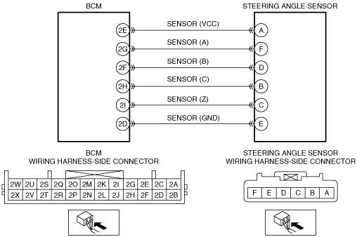
• Short to power supply in wiring harness between the following terminals:
• Open circuit in wiring harness between the following terminals:
• Steering angle sensor malfunction
• BCM malfunction
|
|
![]() |
Diagnostic Procedure
STEP |
INSPECTION |
ACTION |
|
---|---|---|---|
1
|
CONFIRM BCM DTC
• Clear the DTC using the M-MDS.
(See CLEARING DTC [BCM].)
• Start the engine and drive the vehicle at 10 km/h {6.2 mph} or more.
• Perform the BCM DTC inspection using the M-MDS.
(See DTC INSPECTION [BCM].)
• Is the same DTC present?
|
Yes
|
Go to the next step.
|
No
|
Go to Step 9.
|
||
2
|
INSPECT STEERING ANGLE SENSOR CONNECTOR AND TERMINALS
• Switch the ignition to off.
• Disconnect the negative battery cable.
• Disconnect the steering angle sensor connector.
• Inspect the connector and terminals (corrosion, damage, pin disconnection).
• Is there any malfunction?
|
Yes
|
Repair or replace the connector or terminals, then go to Step 8.
|
No
|
Go to the next step.
|
||
3
|
INSPECT BCM CONNECTOR AND TERMINALS
• Disconnect the BCM connector.
• Inspect the connector and terminals (corrosion, damage, pin disconnection).
• Is there any malfunction?
|
Yes
|
Repair or replace the connector or terminals, then go to Step 8.
|
No
|
C0051:2F/C0052:11/C0053:11/C0054:11/C0055:11:
• Go to the next step.
C0052:13/C0053:13/C0054:13/C0055:13:
• Go to Step 6.
|
||
4
|
INSPECT STEERING ANGLE SENSOR CIRCUIT FOR SHORT TO GROUND
• Steering angle sensor and BCM connectors are disconnected.
• Inspect for continuity between the following terminals (wiring harness-side) and body ground:
• Is there continuity?
|
Yes
|
Repair or replace the wiring harness for a possible short to ground, then go to Step 8.
|
No
|
C0051:2F:
• Go to the next step.
C0052:11/C0053:11/C0054:11/C0055:11:
• Go to Step 7.
|
||
5
|
INSPECT STEERING ANGLE SENSOR CIRCUIT FOR SHORT TO POWER SUPPLY
• Steering angle sensor and BCM connectors are disconnected.
• Reconnect the negative battery cable.
• Switch the ignition to ON.
• Measure the voltage at the following terminals (wiring harness-side):
• Is there any voltage?
|
Yes
|
Repair or replace the wiring harness for a possible short to power supply, then go to Step 8.
|
No
|
Go to the next step.
|
||
6
|
INSPECT STEERING ANGLE SENSOR SIGNAL CIRCUIT FOR OPEN CIRCUIT
• Steering angle sensor and BCM connectors are disconnected.
• Switch the ignition to off.
• Disconnect the negative battery cable.
• Inspect for continuity between the following terminals (wiring harness-side):
• Is there continuity?
|
Yes
|
Go to the next step.
|
No
|
Repair or replace the wiring harness for a possible open circuit, then go to Step 8.
|
||
7
|
INSPECT STEERING ANGLE SENSOR
• Reconnect the steering angle sensor and BCM connectors.
• Reconnect the negative battery cable.
• Inspect the steering angle sensor.
• Is there any malfunction?
|
Yes
|
Replace the steering angle sensor, then go to the next step.
|
No
|
Go to the next step.
|
||
8
|
VERIFY TROUBLESHOOTING COMPLETED
• Make sure to reconnect the disconnected connectors.
• Reconnect the negative battery cable.
• Clear the DTC using the M-MDS.
(See CLEARING DTC [BCM].)
• Start the engine and drive the vehicle at 10 km/h {6.2 mph} or more.
• Perform the BCM DTC inspection using the M-MDS.
(See DTC INSPECTION [BCM].)
• Is the same DTC present?
|
Yes
|
Replace the BCM, then go to the next step.
|
No
|
Go to the next step.
|
||
9
|
VERIFY THAT NO OTHER DTCs ARE PRESENT
• Are any DTCs present?
|
Yes
|
Go to the applicable DTC inspection.
(See DTC TABLE [BCM].)
|
No
|
DTC troubleshooting completed.
|