 |
am3zzw00005081
BODY CONTROL MODULE (BCM) REMOVAL/INSTALLATION [L.H.D.]
id0940008004b4
ATX
1. Perform the BCM configuration when replacing it. (See BODY CONTROL MODULE (BCM) CONFIGURATION.)
2. Disconnect the negative battery cable.
3. Remove the following parts:
4. Set the bonnet release lever out of the way. (See BONNET LATCH AND RELEASE LEVER REMOVAL/INSTALLATION.)
5. Remove the lower panel. (driver-side) (See LOWER PANEL REMOVAL/INSTALLATION.)
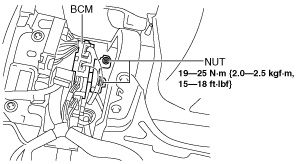
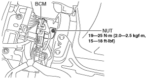
6. Remove the nut shown in the figure.
am3zzw00005081
|
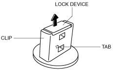
7. Pry off the lock device of the clip while pressing the tab in the position shown in the figure.
am3zzw00005082
|
8. Rotate the clip in the direction of the arrow shown in the figure.
am3uuw00004488
|
9. Remove the clip by pulling it in the direction of the arrow shown in the figure.
am3uuw00004489
|
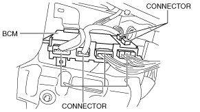
10. Disconnect the connectors shown in the figure.
am3zzw00005083
|
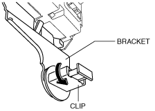
11. While pressing the tab shown in the figure, pull the bracket in the direction of the arrow and remove it.
am3uuw00004491
|
12. Remove the BCM.
13. Install in the reverse order of removal.
MTX
1. Perform the BCM configuration when replacing it. (See BODY CONTROL MODULE (BCM) CONFIGURATION.)
2. Disconnect the negative battery cable.
3. Remove the following parts:
4. Set the bonnet release lever out of the way. (See BONNET LATCH AND RELEASE LEVER REMOVAL/INSTALLATION.)
5. Remove the lower panel. (driver-side) (See LOWER PANEL REMOVAL/INSTALLATION.)
6. Set the starter cut relay out of the way. (with advanced keyless entry and push button start system) (See STARTER CUT RELAY REMOVAL/INSTALLATION [MTX].)
7. Remove the nuts shown in the figure.
am3zzw00005084
|
8. Pry off the lock device of the clip while pressing the tab in the position shown in the figure.
am3zzw00005082
|
9. Rotate the clip in the direction of the arrow shown in the figure.
am3uuw00004488
|
10. Remove the clip by pulling it in the direction of the arrow shown in the figure.
am3uuw00004489
|
11. Disconnect the connectors shown in the figure.
am3zzw00005083
|
12. While pressing the tab shown in the figure, pull the bracket in the direction of the arrow and remove it.
am3uuw00004491
|
13. Remove the BCM.
14. Install in the reverse order of removal.