 |
am3uuw00004313
REQUEST SWITCH INSPECTION
id091400515400
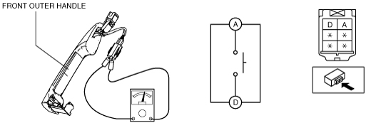
Outer handle
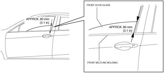
1. To access the glass installation bolt, position the front door glass so that the distance from the top of the front door glass to the upper part of the front beltline molding is approx. 80 mm {3.1 in}.
am3uuw00004313
|
2. Disconnect the negative battery cable.
3. Remove the following parts:
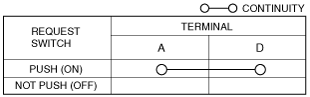
4. Verify the continuity of request switch terminals A and D.
am3zzw00006490
|
5. Verify that the continuity is as indicated in the table.
am3uuw00004727
|
Liftgate
1. Disconnect the negative battery cable.
2. Remove the inboard light. (See INBOARD LIGHT REMOVAL/INSTALLATION.)
3. Remove the request switch(liftgate). (See REQUEST SWITCH REMOVAL/INSTALLATION.)
4. Verify the continuity of request switch terminals A and B.
am3uuw00004728
|
5. Verify that the continuity is as indicated in the table.
am3uuw00004729
|