 |
am3zzw00006180
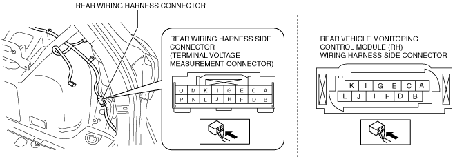
REAR VEHICLE MONITORING CONTROL MODULE INSPECTION
id092200146100
1. Remove the following parts:
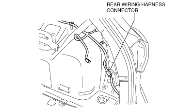
2. Measure the rear vehicle monitoring control module terminal voltage using the rear wiring harness connector in the position shown in the figure.
am3zzw00006180
|
Terminal Voltage Table (Reference)
Rear vehicle monitoring control module (RH)
am3zzw00008804
|
|
Rear wiring harness connector side terminal* |
Rear vehicle monitoring CM (RH) side terminal |
Signal |
Connected to |
Measurement condition |
Voltage (V) |
Inspection item(s) |
|
|---|---|---|---|---|---|---|---|
|
A
|
—
|
—
|
—
|
—
|
—
|
—
|
|
|
B
|
—
|
—
|
—
|
—
|
—
|
—
|
|
|
C
|
—
|
—
|
—
|
—
|
—
|
—
|
|
|
D
|
—
|
—
|
—
|
—
|
—
|
—
|
|
|
E
|
F
|
Power supply
|
Fuse
|
Switch the ignition to ON
|
+B
|
• Fuse
• Related wiring harness
|
|
|
Switch the ignition to off
|
1.0 or less
|
||||||
|
F
|
F
|
—
|
—
|
—
|
—
|
—
|
|
|
G
|
—
|
—
|
—
|
—
|
—
|
—
|
|
|
H
|
—
|
—
|
—
|
—
|
—
|
—
|
|
|
I
|
—
|
—
|
—
|
—
|
—
|
—
|
|
|
J
|
—
|
—
|
—
|
—
|
—
|
—
|
|
|
K
|
D
|
RVM switch signal
|
RVM switch
|
Switch the ignition to ON
|
RVM switch pressed
|
1.0 or less
|
• RVM switch
• Related wiring harness
|
|
RVM switch not pressed
|
+B
|
||||||
|
L
|
—
|
—
|
—
|
—
|
—
|
—
|
|
|
M
|
H
|
Ground
|
Body ground
|
Under any condition
|
1.0 or less
|
• Related wiring harness
|
|
|
N
|
—
|
—
|
—
|
—
|
—
|
—
|
|
|
O
|
—
|
—
|
—
|
—
|
—
|
—
|
|
|
P
|
—
|
—
|
—
|
—
|
—
|
—
|
|
|
—
|
A
|
CAN2_L
|
Rear vehicle monitoring CM (LH)
|
Terminal used for communication therefore determination based on terminal voltage is not possible.
|
|||
|
—
|
C
|
CAN2_H
|
Rear vehicle monitoring CM (LH)
|
Terminal used for communication therefore determination based on terminal voltage is not possible.
|
|||
|
—
|
I
|
CAN_L
|
CAN system related module
|
Terminal used for communication therefore determination based on terminal voltage is not possible.
|
|||
|
—
|
L
|
CAN_H
|
CAN system related module
|
Terminal used for communication therefore determination based on terminal voltage is not possible.
|
|||
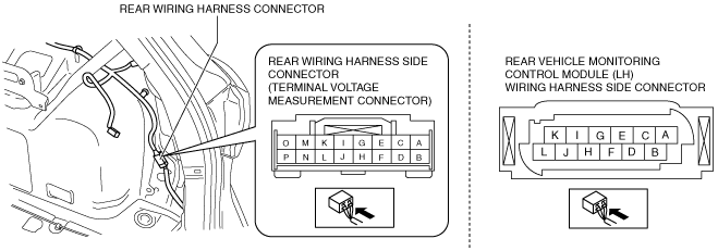
Terminal Voltage Table (Reference)
Rear vehicle monitoring control module (LH)
am3zzw00008805
|
|
Rear wiring harness connector side terminal* |
Rear vehicle monitoring CM (LH) side terminal |
Signal |
Connected to |
Measurement condition |
Voltage (V) |
Inspection item(s) |
|
|---|---|---|---|---|---|---|---|
|
A
|
A
|
—
|
—
|
—
|
—
|
—
|
|
|
B
|
B
|
—
|
—
|
—
|
—
|
—
|
|
|
C
|
C
|
—
|
—
|
—
|
—
|
—
|
|
|
D
|
D
|
—
|
—
|
—
|
—
|
—
|
|
|
E
|
E
|
Power supply
|
Fuse
|
Switch the ignition to ON
|
+B
|
• Fuse
• Related wiring harness
|
|
|
Switch the ignition to off
|
1.0 or less
|
||||||
|
F
|
F
|
—
|
—
|
—
|
—
|
—
|
|
|
G
|
C
|
RVM warning indicator light ground signal (RH)
|
RVM warning indicator light (RH)
|
Under any condition
|
1.0 or less
|
• RVM warning indicator light LED (RH)
• Related wiring harness
|
|
|
H
|
D
|
RVM warning indicator light signal (RH)
|
RVM warning indicator light (RH)
|
Switch the ignition to ON
|
LED off
|
1.0 or less
|
• RVM warning indicator light LED (RH)
• Related wiring harness
|
|
LED on
|
3.0—5.0
|
||||||
|
I
|
G
|
RVM warning indicator light ground signal (LH)
|
RVM warning indicator light (LH)
|
Under any condition
|
1.0 or less
|
• RVM warning indicator light LED (LH)
• Related wiring harness
|
|
|
J
|
K
|
RVM warning indicator light signal (LH)
|
RVM warning indicator light (LH)
|
Switch the ignition to ON
|
LED off
|
1.0 or less
|
• RVM warning indicator light (LH)
• Related wiring harness
|
|
LED on
|
3.0—5.0
|
||||||
|
K
|
—
|
—
|
—
|
—
|
—
|
—
|
|
|
L
|
—
|
—
|
—
|
—
|
—
|
—
|
|
|
M
|
H
|
Ground
|
Body ground
|
Under any condition
|
1.0 or less
|
• Related wiring harness
|
|
|
N
|
—
|
—
|
—
|
—
|
—
|
—
|
|
|
O
|
—
|
—
|
—
|
—
|
—
|
—
|
|
|
P
|
—
|
—
|
—
|
—
|
—
|
—
|
|
|
—
|
L
|
CAN2_H
|
Rear vehicle monitoring CM (RH)
|
Terminal used for communication therefore determination based on terminal voltage is not possible.
|
|||
|
—
|
I
|
CAN2_L
|
Rear vehicle monitoring CM (RH)
|
Terminal used for communication therefore determination based on terminal voltage is not possible.
|
|||