ENGINE DISASSEMBLY/ASSEMBLY [ZJ, ZY, Z6]
id0110b1800500
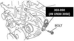
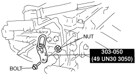
1. Using the bolts part number 99794 1025 or M10×1.25, length 25 mm {0.98 in} to install the SST to the position shown in the figure, hang the engine and transaxle, and then take it down from the engine jack.
-
Caution
-
• When attaching the SST in the engine rear side, install a suitable nut between the engine and the SST.
-
Tightening torque
-
38—51 N·m {3.9—5.2 kgf·m, 29—37 ft·lbf}
2. Remove following parts:
- (1) Starter (See STARTER REMOVAL/INSTALLATION [ZJ, ZY, Z6].)
- (2) Joint shaft (See JOINT SHAFT REMOVAL/INSTALLATION [ZJ, ZY, Z6, LF, L3, L3 Turbo, MZR-CD (RF Turbo)].)
- (3) Transaxle (See AUTOMATIC TRANSAXLE REMOVAL/INSTALLATION (ZY, Z6) [FN4A-EL].) (See MANUAL TRANSAXLE REMOVAL/INSTALLATION [F35M-R].)
- (4) Exhaust manifold (See EXHAUST SYSTEM REMOVAL/INSTALLATION [ZJ, ZY, Z6].)
- (5) Generator (See GENERATOR REMOVAL/INSTALLATION [ZJ, ZY, Z6].)
- (6) P/S oil pump (with mechanical type) (See POWER STEERING OIL PUMP REMOVAL/INSTALLATION [ZJ, Z6].)
- (7) Fuel hose, fuel distributor and fuel injector (See FUEL INJECTOR REMOVAL/INSTALLATION [ZJ, ZY, Z6].)
- (8) Intake manifold (See INTAKE-AIR SYSTEM REMOVAL/INSTALLATION [ZJ, ZY, Z6].)
- (9) Ignition coils (See IGNITION COIL REMOVAL/INSTALLATION [ZJ, ZY, Z6].)
- (10) CKP sensor (See CRANKSHAFT POSITION (CKP) SENSOR REMOVAL/INSTALLATION [ZJ, ZY, Z6].)
3. Install in the reverse order of removal.