|
am3zzw00000615
EXHAUST SYSTEM REMOVAL/INSTALLATION[ZJ, ZY, Z6]
id0115c1800200
1. Remove the battery cover. (See BATTERY REMOVAL/INSTALLATION[ZJ, ZY, Z6].)
2. Disconnect the negative battery cable.
3. Before disconnect the engine coolant hose, drain the engine coolant. (See ENGINE COOLANT REPLACEMENT[ZJ, ZY, Z6].) (with throttle valve actuator)
4. Remove the under cover.
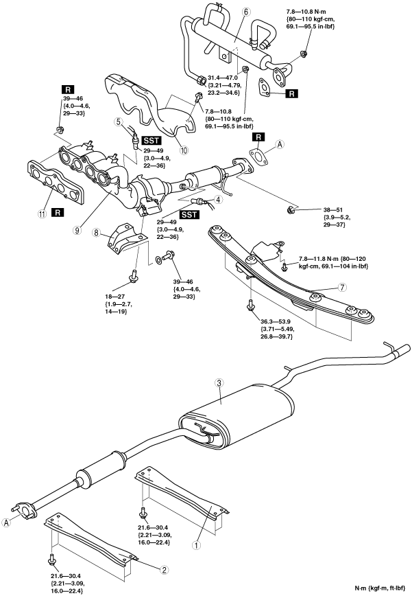
5. Remove in the order indicated in the table.
6. Install in the reverse order of removal.
7. Inspect the front wheel alignment and adjust it if necessary. (See FRONT WHEEL ALIGNMENT.)
Without throttle valve actuator
am3zzw00000615
|
|
1
|
Rear tunnel member
|
|
2
|
Front tunnel member
|
|
3
|
Main silencer
|
|
4
|
Rear HO2S
|
|
5
|
Front HO2S
|
|
6
|
Member
|
|
7
|
Exhaust manifold bracket
|
|
8
|
Exhaust manifold
|
|
9
|
Exhaust manifold insulator
|
|
10
|
Exhaust manifold gasket
|
With throttle valve actuator
am3zzw00003387
|
|
1
|
Rear tunnel member
|
|
2
|
Front tunnel member
|
|
3
|
Main silencer
|
|
4
|
Rear HO2S
|
|
5
|
Front HO2S
|
|
6
|
EGR cooler
|
|
7
|
Member
|
|
8
|
Exhaust manifold bracket
|
|
9
|
Exhaust manifold
|
|
10
|
Exhaust manifold insulator
|
|
11
|
Exhaust manifold gasket
|
Exhaust Manifold/Exhaust Manifold Insulator Removal Note
1. Remove the front wheels and tires.
2. Perform the following procedure for easier access.
3. Disconnect the steering shaft from the steering gear and linkage side. (See STEERING GEAR AND LINKAGE REMOVAL/INSTALLATION.)
4. Disconnect the pressure hose and the return hose. (See STEERING GEAR AND LINKAGE REMOVAL/INSTALLATION.)
5. Remove the No.1 engine mount rubber. (See ENGINE REMOVAL/INSTALLATION[ZJ, ZY, Z6].)
6. Loosen the exhaust manifold insulator bolts.
7. Move the exhaust manifold insulator slightly out of the way and loosen the exhaust manifold nuts.
8. Remove the installation bolts of the front stabilizer and front crossmember component. (See FRONT CROSSMEMBER REMOVAL/INSTALLATION.)
9. Loosen the front crossmember component installation bolts and lower the front crossmember component approx. 100 mm {3.94 in}. (See FRONT CROSSMEMBER REMOVAL/INSTALLATION.)
10. Support the flexible pipe with a support wrap or splint as shown in the figure.
am3zzw00000393
|
11. Remove the exhaust manifold together with the insulator by lowering it to the underside of the vehicle.
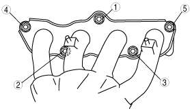
Exhaust Manifold Installation Note
1. Tighten the exhaust manifold installation nuts in the order shown in the figure.
am3zzw00000394
|