FUEL TANK REMOVAL/INSTALLATION[MZ-CD 1.6 (Y6)]
id0114c3801600
-
Warning
-
• Repairing a fuel tank containing fuel is dangerous. Explosion or fire may cause death or serious injury. Always properly steam clean a fuel tank before repairing it.
• As this procedure involves handling fuel additives, be prepared for fuel additive spillage at all times and always observe fuel handling precautions. Failure to follow these instructions may result in personal injury. (High power-Euro 4)
• Eye, hand, ear protection and protective clothing are required to be worn during any general or removal and installation procedure of fuel additive system components. Failure to follow these instructions may result in personal injury. (High power-Euro 4)
• In case of fuel additive fluid contact with the skin or the eyes, flush immediately with water for a minimum of 15 minutes and seek prompt medical attention. Failure to follow these instructions may result in personal injury. (High power-Euro 4)
• If fuel additive fluid is swallowed, call a physician immediately. Rinse mouth immediately with water, do not induce vomiting. Failure to follow these instructions may result in personal injury. (High power-Euro 4)
• Always provide adequate ventilation when working on the fuel additive system or related components. Failure to follow these instructions may result in personal injury. (High power-Euro 4)
• Do not smoke or carry lighted tobacco or open flame of any type when working on or near any fuel related components. Highly flammable vapors are always present and may ignite. Failure to follow these instructions may result in personal injury. (High power-Euro 4)
• A person charged with static electricity could cause a fire or explosion, resulting in death or serious injury. Before draining fuel, make sure to discharge static electricity by touching a vehicle.
-
Caution
-
• Make sure the workshop area in which the vehicle is being worked on is as clean and as dust free as possible. Foreign matter from work on clutches, brakes or from machining or welding operations can contaminate the fuel system and may result in later malfunction. (High power-Euro 4)
• After completing the filling procedure, make sure the fuel additive refill kit and pipes are stored in a dry and secure area away from dust. Foreign matter from work on clutches, brakes or from machining or welding operations can contaminate the fuel additive fluid. (High power-Euro 4)
-
Note
-
• If the fuel is contaminated (gasoline) and must therefore be drained, perform the following procedure (High power‐Euro 4):
-
1. Disconnect the battery to prevent the fuel additive control module from detecting the opening of the fuel‐filler lid and the change in fuel level.
2. Drain the contaminated fuel from the fuel tank using the following procedure.
-
2. Disconnect the breather hose (when the fuel tank is full) or the joint hose (except when the fuel tank is full) from the fuel-filler pipe.
3. Drain the fuel by tilting the breather hose (when the fuel tank is full) or the joint hose (except when the fuel tank is full).
4. Siphon the fuel from the fuel tank using a fuel suction pump.
3. Re‐connect the battery and turn the engine switch on for 10 s, so that the fuel additive control module can detect the empty fuel tank.
4. Turn the engine switch off.
5. Open the fuel‐filler lid and add clean fuel.
6. Turn the engine switch back on again for 10 s.
-
In this way, the fuel additive control module can determine the correct fuel additive injection amount for the clean fuel added.
1. Remove the battery cover. (See BATTERY REMOVAL/INSTALLATION[MZ-CD 1.6 (Y6)].)
2. DIsconnect the negative battery cable.
3. Open the fuel-filler cap.
4. Follow “BEFORE SERVICE PRECAUTION” before performing any work operations to prevent fuel from spilling from the fuel system. (See BEFORE SERVICE PRECAUTION[MZ-CD 1.6 (Y6)].)
5. Drain the fuel using the following procedure.
- (1) Disconnect the breather hose (when the fuel tank is full) or the joint hose (except when the fuel tank is full) from the fuel-filler pipe.
-
- (2) Drain the fuel by tilting the breather hose (when the fuel tank is full) or the joint hose (except when the fuel tank is full).
-
- (3) Siphon the fuel from the fuel tank using a fuel drawing pump.
-
6. Remove the rear seat cushion. (See REAR SEAT REMOVAL/INSTALLATION.)
7. Remove the service hole cover.
8. Disconnect the fuel sender unit connector.
9. Remove the front tunnel member and rear tunnel member. (See EXHAUST SYSTEM REMOVAL/INSTALLATION[MZ-CD 1.6 (Y6)].)
10. Remove the flexible pipe and main silencer joint nuts. (See EXHAUST SYSTEM REMOVAL/INSTALLATION[MZ-CD 1.6 (Y6)].)
11. Remove the main silencer hanger from the mount rubber.
12. Lower the main silencer so that the insulator can be removed. (See EXHAUST SYSTEM REMOVAL/INSTALLATION[MZ-CD 1.6 (Y6)].)
13. Strap the main silencer by rope.
14. Remove the protector.
15. Remove in the order indicated in the table.
16. Install in the reverse order of removal.
17. Inspect all parts by performing “AFTER SERVICE PRECAUTION”. (See AFTER SERVICE PRECAUTION[MZ-CD 1.6 (Y6)].)
|
1
|
Insulator
|
|
2
|
Quick release connector (Type B)
|
|
3
|
Joint hose
|
|
4
|
Breather hose
|
|
5
|
Strap
|
|
6
|
Fuel tank
|
|
7
|
Fuel-filler cap
|
|
8
|
Fuel-filler pipe
|
|
9
|
Quick release connector (Type A)
|
|
10
|
Quick release connector (Type D) (High power-Euro 4)
|
Fuel-filler Pipe Removal Note
1. Remove the rear tire (RH).
2. Remove the rear mudguard (RH).
3. Support the rear crossmember using a transmission jack.
4. Remove the rear shock absorber (RH) lower bolts. (See REAR SHOCK ABSORBER REMOVAL/INSTALLATION.)
5. Loosen the rear crossmember installation nuts (6 locations) and lower the rear crossmember 30 mm {1.2 in}. (See REAR CROSSMEMBER REMOVAL/INSTALLATION.)
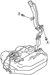
6. Remove the fuel-filler pipe.
Fuel-filler Pipe Installation Note
1. Temporarily tighten bolt A. then tighten in the order of B, then A.
-
Tightening torque
-
9—13 N·m {91.8—132.5 kgf·cm, 79.7—115.0 in·lbf}
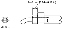
Breather Hose Installation Note
1. Install the breather hose and clamp as shown in the figure.
Joint Hose Installation Note
1. Install the joint hose and clamp as shown in the figure.