MANIFOLD ABSOLUTE PRESSURE (MAP) SENSOR INSPECTION[L3 Turbo]
id0140b6800900
-
Note
-
• Perform the following inspection only when directed.
• The following vacuum values are indicated by relative pressure from the MAP sensor.
1. Connect the M-MDS to the DLC‐2.
2. Turn the ignition switch to ON (Engine off).
3. Select MAP PID on the M-MDS.
4. Verify that the MAP PID (pressure) and barometric pressure are practically equal.
-
• If not as verified, perform the “Circuit Open/Short Inspection”.
-
― If there is no open or short circuit, replace the MAP sensor.
• If as verified, go to next step.
5. Apply vacuum of–25.0 kPa {–187 mmHg, –7.38 inHg} to the MAP sensor, and verify that the MAP variation from that of Step 4 isapprox. 25.0 kPa {187 mmHg, 7.38 inHg}.
-
• If not as verified, perform the “Circuit Open/Short inspection”.
-
Circuit Open/Short Inspection
1. Disconnect the PCM connector. (See PCM REMOVAL/INSTALLATION[L3 Turbo].)
2. Inspect the following wiring harnesses for an open or short circuit. (Continuity check)
Open circuit
-
• If there is no continuity, there is an open circuit. Repair or replace the wiring harness.
-
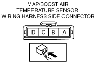
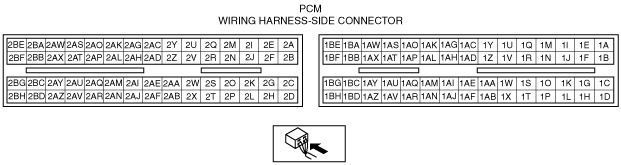
― MAP/boost air temperature sensor terminal A and PCM terminal 2AV
― MAP/boost air temperature sensor terminal C and PCM terminal 2AU
― MAP/boost air temperature sensor terminal D and PCM terminal 2AG
Short circuit
-
• If there is continuity, there is a short circuit. Repair or replace the wiring harness.
-
― MAP/boost air temperature sensor terminal A and power supply.
― MAP/boost air temperature sensor terminal C and body ground.
― MAP/boost air temperature sensor terminal D and power supply.
― MAP/boost air temperature sensor terminal D and body ground