BOOST AIR TEMPERATURE SENSOR INSPECTION[L3 Turbo]
id0140b6802100
Resistance Inspection
-
Note
-
• Before performing the following inspection, make sure to follow the procedure as indicated in the troubleshooting flowchart. (See
HOW TO USE THIS MANUAL.)
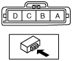
1. Disconnect MAP/boost air temperature sensor.
2. Measure the resistance between the MAP/boost air temperature sensor terminals A and B using a tester.
-
• If the MAP/boost air temperature sensor is normal, but PID are out of specification, perform the “Circuit Open/Short Inspection”.
Specification
|
Ambient temperature (°C {°F})
|
Resistance (kilohm)
|
|
20 {68}
|
2.4—2.7
|
|
60 {140}
|
0.59—0.64
|
Circuit Open/Short Inspection
1. Disconnect the PCM connector. (See PCM REMOVAL/INSTALLATION[L3 Turbo].)
2. Inspect the following wiring harnesses for an open or short circuit. (Continuity check)
Open circuit
-
• If there is no continuity, there is an open circuit. Repair or replace the wiring harness.
-
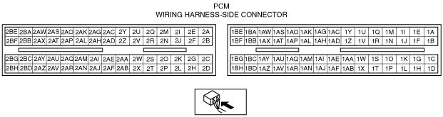
― MAP/boost air temperature sensor terminal A and PCM terminal 2AV
― MAP/boost air temperature sensor terminal B and PCM terminal 2N
― MAP/boost air temperature sensor terminal C and PCM terminal 2AU
Short circuit
-
• If there is continuity, there is a short circuit. Repair or replace the wiring harness.
-
― MAP/boost air temperature sensor terminal A and power supply
― MAP/boost air temperature sensor terminal B and power supply
― MAP/boost air temperature sensor terminal B and body ground
― MAP/boost air temperature sensor terminal C and body ground