DTC C1277, C1278, C1306, C1307 [DYNAMIC STABILITY CONTROL (DSC)]


id0402b2808000

DTC
C1277, C1278, C1306, C1307
Steering angle sensor
DETECTION CONDITION
•  C 1277
―  Output voltage from steering angle sensor signals 1 and 2 is other than 0.25—0.75 V or 4.25—4.75 V
―  Signal from steering angle sensor changes when speed is not within specification (14 pulses/7 ms (3000°/S) or more)
•  C 1278
―  The steering angle sensor detects signal modulation or steering angle that exceeds specification.
•  C 1306
―  The neutral position of the steering angle cannot be estimated from the signals from the ABS wheel-speed sensors and the combined sensor.
•  C 1307
―  The signal from the steering angle sensor remains unchanged when the steering angle is turned to the right and left.
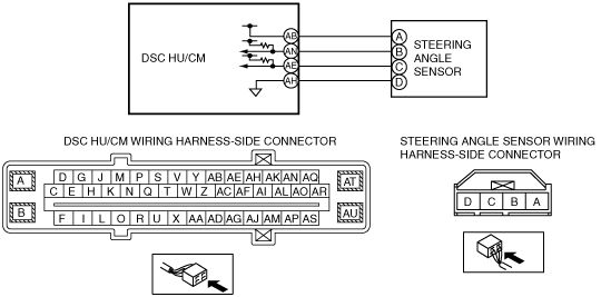
POSSIBLE CAUSE
•  Improper installation or positioning of the steering angle sensor
•  Open circuit in the wiring harness between DSC HU/CM terminal AB and steering angle sensor terminal A
•  Open circuit in the wiring harness between DSC HU/CM terminal AE and steering angle sensor terminal C, short to battery or to ground
•  Open circuit in the wiring harness between DSC HU/CM terminal AN and steering angle sensor terminal B, short to battery or to ground
•  Open circuit in the wiring harness between DSC HU/CM terminal AH and steering angle sensor terminal D
•  Signal error from the ABS wheel-speed sensor
•  Signal error from the combined sensor
•  Signal errors from sensors due to rough road driving
•  Steering angle sensor malfunction
•  Poor connection at connectors (female terminal)

Diagnostic procedure

STEP

INSPECTION

ACTION

1
INSPECT STEERING ANGLE SENSOR POWER SUPPLY FOR OPEN CIRCUIT
•  Turn the ignition switch to the ON position.
•  Measure the voltage between the steering angle sensor terminal A and body ground.
•  Is the voltage B+?
Yes
Go to the next step.
No
Repair or replace the wiring harness, then go to Step 8.
2
INSPECT STEERING ANGLE SENSOR GROUND FOR OPEN CIRCUIT
•  Turn the ignition switch off.
•  Inspect for continuity between the steering angle sensor terminal D and body ground.
•  Is there continuity?
Yes
Go to the next step.
No
Repair or replace the wiring harness, then go to Step 8.
3
INSPECT STEERING ANGLE SENSOR SIGNAL FOR OPEN CIRCUIT
•  Disconnect the DSC HU/CM connectors.
•  Inspect for continuity between the DSC HU/CM connectors (vehicle harness-side) and the following steering angle sensor connector terminals:
―  Steering angle sensor (Sensor 1 system): AN—B
―  Steering angle sensor (Sensor 2 system): AE—C
•  Is there continuity?
Yes
Go to the next step.
No
Repair or replace the wiring harness, then go to Step 8.
4
INSPECT STEERING ANGLE SENSOR SIGNAL FOR SHORT TO GROUND
•  Disconnect the steering angle sensor connectors
•  Inspect for continuity between the following steering angle sensor connector terminals (vehicle harness-side) and body ground:
―  Steering angle sensor (Sensor 1 system): B—Body ground
―  Steering angle sensor (Sensor 2 system): C—Body ground
•  Is there continuity?
Yes
Repair or replace the wiring harness, then go to Step 8.
No
Go to the next step.
5
INSPECT STEERING ANGLE SENSOR SIGNAL FOR SHORT TO POWER SUPPLY CIRCUIT
•  Measure voltage between the following steering angle sensor connector terminals (vehicle harness-side) and body ground:
―  Steering angle sensor (Sensor 1 system): B—Body ground
―  Steering angle sensor (Sensor 2 system): C—Body ground
•  Is the voltage 1 V or less?
Yes
Go to the next step.
No
Repair or replace the wiring harness, then go to Step 8.
6
INSPECT FOR IMPROPER INSTALLATION OF STEERING ANGLE SENSOR
•  Is the installation normal?
Yes
Go to the next step.
No
Repair installation or replace the steering angle sensor, then go to Step 8.
7
INSPECT STEERING ANGLE SENSOR
•  Reconnect all disconnected connectors.
•  Inspect the steering angle sensor.
•  Is the steering angle sensor normal?
Yes
Go to the next step.
No
Replace the steering angle sensor, then go to the next step.
8
VERIFY THAT THE SAME DTC IS NOT PRESENT
•  Clear the DTCs from the memory.
•  Start the engine and drive the vehicle at 10 km/h {6.2 mph} or more.
•  Are the same DTCs present?
Yes
Repeat the inspection from Step 1.
If the malfunction recurs, replace the DSC CM, then go to the next step.
No
Go to the next step.
9
VERIFY THAT NO OTHER DTCS ARE PRESENT
•  Are any other DTCs output?
Yes
Go to the applicable DTC inspection.
No
DTC troubleshooting completed.