 |
am3zzw00001632
ON-BOARD DIAGNOSIS [DYNAMIC STABILITY CONTROL (DSC)]
id0402b2800200
On-Board Diagnostic (OBD) Test Description
Read/clear diagnostic results
PID/Data monitor and record
Active command modes
Reading DTCs Procedure
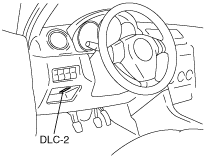
1. Connect the M-MDS to the DLC-2 connector.
am3zzw00001632
|
2. After the vehicle is identified, select the following items from the initial screen of the M-MDS.
3. Verify the DTC according to the directions on the screen.
4. After completion of repairs, clear all DTCs stored in the DSC. (See Clearing DTCs Procedures.)
Clearing DTCs Procedures
1. Connect the M-MDS to the DLC-2 connector.
am3zzw00001632
|
2. After the vehicle is identified, select the following items from the initial screen of the M-MDS.
3. Verify the DTC according to the directions on the screen.
4. Press the clear button on the DTC screen to clear the DTC.
5. Verify that no DTCs are displayed.
PID/Data Monitor and Record Procedure
1. Connect the M-MDS to the DLC-2 connector.
am3zzw00001632
|
2. After the vehicle is identified, select the following items from the initial screen of the M-MDS.
3. Select the applicable PID from the PID table.
4. Verify the PID data according to the directions on the screen.
Active Command Modes Procedure
1. Connect the M-MDS to the DLC-2 connector.
am3zzw00001632
|
2. After the vehicle is identified, select the following items from the initial screen of the M-MDS.
3. Select the active command modes from the PID table.
4. Perform the active command modes, inspect the operations for each parts.
DTC Table
|
DTC |
System malfunction location |
Page |
|---|---|---|
|
M-MDS |
||
|
B1317
|
Power supply system
|
|
|
B1318
|
Power supply system
|
|
|
B1342
|
DSC CM (internal malfunction)
|
|
|
B2141
|
Vehicle data not recorded
|
|
|
B2741
|
Combined sensor (internal malfunction)
|
|
|
C1093
|
DSC OFF switch
|
|
|
C1095
|
Pump motor, motor relay
|
|
|
C1141
|
LF ABS sensor rotor
|
|
|
C1142
|
RF ABS sensor rotor
|
|
|
C1143
|
LR ABS sensor rotor
|
|
|
C1144
|
RR ABS sensor rotor
|
|
|
C1145
|
RF ABS wheel-speed sensor
|
|
|
C1155
|
LF ABS wheel-speed sensor
|
|
|
C1165
|
RR ABS wheel-speed sensor
|
|
|
C1175
|
LR ABS wheel-speed sensor
|
|
|
C1233
|
LF ABS wheel-speed sensor/ABS sensor rotor
|
|
|
C1234
|
RF ABS wheel-speed sensor/ABS sensor rotor
|
|
|
C1235
|
RR ABS wheel-speed sensor/ABS sensor rotor
|
|
|
C1236
|
LR ABS wheel-speed sensor/ABS sensor rotor
|
|
|
C1267
|
DSC CM (internal malfunction)
|
|
|
C1277
|
Steering angle sensor
|
|
|
C1278
|
Combined sensor system
|
|
|
C1279
|
Combined sensor system
|
|
|
C1280
|
Combined sensor system
|
|
|
C1281
|
Combined sensor system
|
|
|
C1282
|
Combined sensor system
|
|
|
C1288
|
Brake fluid pressure sensor
|
|
|
C1306
|
Steering angle sensor
|
|
|
C1307
|
Steering angle sensor
|
|
|
C1440
|
Brake fluid pressure sensor
|
|
|
C1446
|
Brake switch
|
|
|
C1470
|
TCS control system
|
|
|
C1730
|
Brake fluid pressure sensor power supply system
|
|
|
C1994
|
TCS/DSC control system
|
|
|
C2778
|
Combined sensor system
|
|
|
C2785
|
Combined sensor system (unperformed initialization procedure)
|
|
|
U1900
|
CAN line
|
|
|
U1901
|
Combined sensor system (CAN2 line malfunction)
|
|
|
U2012
|
CAN line
|
|
|
U2023
|
CAN line
|
|
|
U2202
|
CAN line
|
|
|
U2527
|
Combined sensor system (CAN2 line malfunction)
|
PID/DATA Monitor Table
|
PID name (definition) |
Unit/Condition |
Operation condition (reference) |
Action |
DSC HU/CM terminal |
|---|---|---|---|---|
|
BOO_ABS
(Brake pedal switch input)
|
On/Off
|
• Brake pedal depressed: On
• Brake pedal released: Off
|
Inspect the brake switch.
|
—
|
|
CCNTABS
(Number of continuous codes)
|
—
|
• DTCs detected: 1—255
• No DTCs detected: 0
|
Perform the DTC inspection.
(See DTC Table.)
|
—
|
|
ESP_VOLT
|
V
|
• Ignition switch at ON: Approx. 12.2 V
• Idling: Approx. 14.1 V
|
Inspect the battery.
|
—
|
|
LAT_ACCL
|
G
|
• Vehicle stopped or driving at constant speed: 0 G
• Cornering to right: Changes 0 G—positive
• Cornering to left: Changes 0 G—negative
|
Inspect the combined sensor.
(See COMBINED SENSOR INSPECTION.)
|
—
|
|
LF_WSPD
(Left front ABS wheel-speed sensor input)
|
KPH, MPH
|
• Vehicle stopped: 0 KPH, 0 MPH
• Vehicle running: vehicle speed
|
Inspect the ABS wheel-speed sensor.
|
I, F
|
|
LR_WSPD
(Left rear ABS wheel-speed sensor input)
|
KPH, MPH
|
• Vehicle stopped: 0 KPH, 0 MPH
• Vehicle running: vehicle speed
|
Inspect the ABS wheel-speed sensor.
|
AJ, AG
|
|
MPRETDR
|
Pa
|
• Brake pedal depressed: Changes according to the brake fluid pressure
|
Inspect the DSC HU/CM.
(See DSC HU/CM INSPECTION.)
|
—
|
|
RF_WSPD
(Right front ABS wheel-speed sensor input)
|
KPH, MPH
|
• Vehicle stopped: 0 KPH, 0 MPH
• Vehicle running: vehicle speed
|
Inspect the ABS wheel-speed sensor.
|
AP, AS
|
|
RR_WSPD
(Right rear ABS wheel-speed sensor input)
|
KPH, MPH
|
• Vehicle stopped: 0 KPH, 0 MPH
• Vehicle running: vehicle speed
|
Inspect the ABS wheel-speed sensor.
|
O, R
|
|
SWA_POS
|
°
|
• Steering wheel in neutral position (not turned): 0°
• Steering wheel turned to left: Changes 0°—negative
• Steering wheel turned to right: Changes 0°—positive
|
Inspect the steering angle sensor.
|
AE, AN
|
|
TCYC_FS
|
On/Off
|
• Solenoid valve activated: On
• Solenoid valve not activated: Off
|
Inspect the DSC HU/CM.
(See DSC SYSTEM INSPECTION.)
|
—
|
|
TCYC_SW
|
Depressed/Not_Depressed
|
• DSC OFF switch depressed: Depressed
• DSC OFF switch not depressed: Not_Depressed
|
Inspect the DSC OFF switch.
(See DSC OFF SWITCH INSPECTION.)
|
AD
|
|
YAW_RATE
|
°/s
|
• Vehicle stopped or driving straight: 0 °/s
• Cornering to left: Changes 0 °/s—negative
• Cornering to right: Changes 0 °/s—positive
|
Inspect the combined sensor.
(See COMBINED SENSOR INSPECTION.)
|
—
|
Active Command Modes Table
|
Command name |
Output part |
Operation |
Operating condition |
|---|---|---|---|
|
PMP_MOTOR
|
Pump motor
|
On/Off
|
Ignition switch at ON
|
|
RF_OUTLET
|
RF outlet solenoid valve
|
||
|
RF_INLET
|
RF inlet solenoid valve
|
||
|
LF_OUTLET
|
LF outlet solenoid valve
|
||
|
LF_INLET
|
LF inlet solenoid valve
|
||
|
RR_OUTLET
|
RR outlet solenoid valve
|
||
|
RR_INLET
|
RR inlet solenoid valve
|
||
|
LR_OUTLET
|
LR outlet solenoid valve
|
||
|
LR_INLET
|
LR inlet solenoid valve
|
||
|
LF_TC_PRV
|
LF stability control solenoid valve
|
||
|
RF_TC_PRV
|
RF stability control solenoid valve
|
||
|
LF_TC_SWV
|
LF traction control solenoid valve
|
||
|
RF_TC_SWV
|
RF traction control solenoid valve
|
||
|
MCYL_S_CAL
|
Brake fluid pressure sensor initialization start-up
|
True/False
|
|
|
LATACCEL
|
Combined sensor (lateral acceleration) initialization start-up
|