 |
am3zzw00001233
SOLENOID VALVE INSPECTION[FN4A-EL]
id0517a1801900
Resistance Inspection (On-Vehicle Inspection)
1. Remove the battery cover. (See BATTERY REMOVAL/INSTALLATION[ZJ, ZY, Z6].) (See BATTERY REMOVAL/INSTALLATION[LF, L3].)
2. Disconnect the negative battery cable.
3. Remove the under cover.
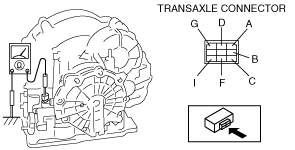
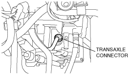
4. Disconnect the transaxle connector.
am3zzw00001233
|
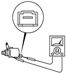
5. Measure the resistance between the following terminals.
am3zzw00001234
|
Solenoid valve resistance (ATF temperature: –40—150 °C {–40—302 °F})
|
Terminal |
Solenoid valve |
Resistance (ohm) |
|---|---|---|
|
A—GND
|
Shift solenoid A
|
1.0—4.2
|
|
C—GND
|
Shift solenoid B
|
1.0—4.2
|
|
G—GND
|
Shift solenoid C
|
1.0—4.2
|
|
B—GND
|
Shift solenoid D
|
10.9—26.2
|
|
F—GND
|
Shift solenoid E
|
10.9—26.2
|
|
D—I
|
Pressure control
|
2.4—7.3
|
6. Connect the transaxle connector.
7. Install the under cover.
8. Connect the negative battery cable.
9. Install the battery cover. (See BATTERY REMOVAL/INSTALLATION[ZJ, ZY, Z6].) (See BATTERY REMOVAL/INSTALLATION[LF, L3].)
Operating Inspection
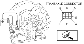
1. Disconnect the transaxle connector.
2. Apply battery positive voltage to the transaxle connector terminals A, B, C, F or G and battery negative voltage to GND, and verify that operating sound is heard from the solenoid.
3. Apply battery positive voltage to the transaxle connector terminal D and battery negative voltage to the transaxle connector terminal I, and verify that operating sound is heard from solenoid.
am3zzw00001235
|
Resistance Inspection (Off-Vehicle Inspection)
1. Remove the control valve body. (See SOLENOID VALVE REMOVAL/INSTALLATION[FN4A-EL].)
2. Measure the resistance of each solenoid valve individually.
3. Install the control valve body. (See SOLENOID VALVE REMOVAL/INSTALLATION[FN4A-EL].)
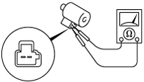
Pressure control solenoid
am3zzw00001236
|
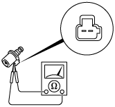
Shift solenoid A, B, C
am3zzw00001237
|
Shift solenoid D, E
am3zzw00001238
|