POWER BRAKE UNIT REMOVAL/INSTALLATION [R.H.D.]
id041100801852
-
Caution
-
• Once the brake switch clearance has automatically been adjusted, it cannot be adjusted again. Therefore, replace the switch with a new one when replacing the power brake unit or performing any procedure that changes the pedal stroke.
• Brake fluid will damage painted surfaces. Be careful not to spill any on painted surfaces. In addition, if there is any brake fluid on the wiring harness, the wire insulation may corrode causing a malfunction such as a short circuit. If brake fluid gets on a painted surface or wiring harness, wash and flush it off completely with water immediately.
-
Note
-
• Tighten the brake pipe flare nut using any commercially available flare nut wrench.
1. Disconnect the negative battery cable. (See NEGATIVE BATTERY CABLE DISCONNECTION/CONNECTION [MZR 1.6].) (See NEGATIVE BATTERY CABLE DISCONNECTION/CONNECTION [SKYACTIV-G 1.5, SKYACTIV-G 2.0, SKYACTIV-G 2.5].) (See NEGATIVE BATTERY CABLE DISCONNECTION/CONNECTION [SKYACTIV-D 1.5].) (See NEGATIVE BATTERY CABLE DISCONNECTION/CONNECTION [SKYACTIV-D 2.2].)
2. For MZR 1.6, SKYACTIV-G 1.5, SKYACTIV-G 2.0 or SKYACTIV-G 2.5, perform the following procedure:
- (1) Remove the plug hole plate. (Except MZR 1.6) (See PLUG HOLE PLATE REMOVAL/INSTALLATION [SKYACTIV-G 1.5, SKYACTIV-G 2.0, SKYACTIV-G 2.5].)
- (2) Remove the windshield wiper arm and blade. (See WINDSHIELD WIPER ARM AND BLADE REMOVAL/INSTALLATION.)
- (3) Remove the cowl grille. (See COWL GRILLE REMOVAL/INSTALLATION.)
- (4) Remove the windshield wiper motor and link. (See WINDSHIELD WIPER MOTOR AND LINK REMOVAL/INSTALLATION.)
- (5) Remove the keyless beeper. (With advanced keyless entry system) (See KEYLESS BEEPER REMOVAL/INSTALLATION.)
- (6) Remove the cowl panel. (See COWL PANEL REMOVAL/INSTALLATION.)
- (7) Remove the insulator. (See EXHAUST SYSTEM REMOVAL/INSTALLATION [MZR 1.6].) (See EXHAUST SYSTEM REMOVAL/INSTALLATION [SKYACTIV-G 1.5, SKYACTIV-G 2.0, SKYACTIV-G 2.5].)
- (8) Remove the master cylinder. (See MASTER CYLINDER REMOVAL/INSTALLATION [R.H.D.].)
3. For SKYACTIV-D 1.5, perform the following procedure:
- (1) Remove the windshield wiper arm and blade. (See WINDSHIELD WIPER ARM AND BLADE REMOVAL/INSTALLATION.)
- (2) Remove the cowl grille. (See COWL GRILLE REMOVAL/INSTALLATION.)
- (3) Remove the windshield wiper motor and link. (See WINDSHIELD WIPER MOTOR AND LINK REMOVAL/INSTALLATION.)
- (4) Remove the keyless beeper. (With advanced keyless entry system) (See KEYLESS BEEPER REMOVAL/INSTALLATION.)
- (5) Remove the cowl panel. (See COWL PANEL REMOVAL/INSTALLATION.)
- (6) Remove the master cylinder. (See MASTER CYLINDER REMOVAL/INSTALLATION [R.H.D.].)
4. For SKYACTIV-D 2.2, perform the following procedure:
- (1) Remove the windshield wiper arm and blade. (See WINDSHIELD WIPER ARM AND BLADE REMOVAL/INSTALLATION.)
- (2) Remove the cowl grille. (See COWL GRILLE REMOVAL/INSTALLATION.)
- (3) Remove the windshield wiper motor and link. (See WINDSHIELD WIPER MOTOR AND LINK REMOVAL/INSTALLATION.)
- (4) Remove the keyless beeper. (With advanced keyless entry system) (See KEYLESS BEEPER REMOVAL/INSTALLATION.)
- (5) Remove the cowl panel. (See COWL PANEL REMOVAL/INSTALLATION.)
- (6) Remove the front under cover No.2. (See FRONT UNDER COVER No.2 REMOVAL/INSTALLATION.)
- (7) Remove the insulator. (See EXHAUST SYSTEM REMOVAL/INSTALLATION [SKYACTIV-D 2.2].)
- (8) Remove the master cylinder. (See MASTER CYLINDER REMOVAL/INSTALLATION [R.H.D.].)
- (9) Remove the engine cover. (See ENGINE COVER REMOVAL/INSTALLATION [SKYACTIV-D 2.2].)
- (10) Disconnect the PCM connector. (See PCM REMOVAL/INSTALLATION [SKYACTIV-D 2.2].)
- (11) Remove the clip from the PCM bracket. (See PCM REMOVAL/INSTALLATION [SKYACTIV-D 2.2].)
- (12) Remove the clip and bolt from the PCM bracket. (See ENGINE MOUNT DISASSEMBLY/ASSEMBLY [SKYACTIV-D 2.2].)
- (13) Remove the PCM component installation bolts. (See ENGINE MOUNT DISASSEMBLY/ASSEMBLY [SKYACTIV-D 2.2].)
- (14) Remove the PCM component.
- (15) Remove the cooler hose (LO) installation nuts. (See REFRIGERANT LINE REMOVAL/INSTALLATION [SKYACTIV-D 2.2].)
-
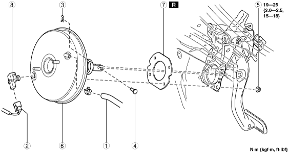
5. Remove in the order indicated in the table.
6. Install in the reverse order of removal.
7. After installation, add brake fluid, bleed the air, and inspect for fluid leakage. (See BRAKE FLUID AIR BLEEDING.)
8. Remove the brake switch. (See BRAKE PEDAL REMOVAL/INSTALLATION [R.H.D.].)
9. Inspect the brake pedal. (See BRAKE PEDAL INSPECTION.)
10. Install a new brake switch. (See BRAKE PEDAL REMOVAL/INSTALLATION [R.H.D.].)
|
1
|
Vacuum hose
|
|
2
|
Power brake unit vacuum sensor connector (vehicles with i-stop)
|
|
3
|
Snap pin
|
|
4
|
Clevis pin
|
|
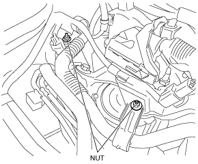
5
|
Nut
|
|
6
|
Power brake unit
|
|
7
|
Gasket
|
|
8
|
Power brake unit vacuum sensor (vehicles with i-stop)
|