|
1
|
VERIFY RELATED SERVICE INFORMATION AVAILABILITY
• Verify related Service Information availability.
• Is any related Service Information available?
|
Yes
|
Perform repair or diagnosis according to the available Service Information.
• If the vehicle is not repaired, go to the next step.
|
|
No
|
Go to the next step.
|
|
2
|
VERIFY RELATED PENDING CODE AND/OR DTC
• Switch the ignition to off, then to ON (engine off).
• Perform the Pending Trouble Code Access Procedure and DTC Reading Procedure.
• Is the PENDING CODE/DTC P0704:00 also present?
|
Yes
|
Go to the applicable PENDING CODE or DTC inspection.
|
|
No
|
Go to the next step.
|
|
3
|
INSPECT INSTALLATION OF CPP SWITCH, CLUTCH STROKE SENSOR AND STARTER INTERLOCK SWITCH
• Inspect if the CPP switch, clutch stroke sensor and starter interlock switch are loosely installed.
• Are the CPP switch, clutch stroke sensor and starter interlock switch installed securely?
|
Yes
|
Go to the next step.
|
|
No
|
Retighten the malfunctioning switch and/or sensor, then go to Step 24.
|
|
4
|
DETERMINE MALFUNCTIONING SYSTEM
-
― PCM PID:
-
• CPP (OFF/ON)
• CPP (%)
― Advanced keyless entry and push button start system PID (Vehicles with advanced keyless entry and push button start system)
-
• START_LC_SW
― PCM terminal voltage (Vehicles without advanced keyless entry and push button start system)
-
• Terminal 1AA
• Is there any malfunction?
|
Yes
|
If the START_LC_SW PID is not normal (Vehicles with advanced keyless entry and push button start system):
• Go to the next step.
If the PCM terminal 1AA voltage is not normal (Vehicles without advanced keyless entry and push button start system):
• Go to the next step.
If the CPP PID (OFF/ON) is not normal:
• Go to Step 10.
If the CPP PID (%) is not normal:
• Go to Step 17.
|
|
No
|
Intermittent concern exists.
• Perform the “INTERMITTENT CONCERN TROUBLESHOOTING” procedure.
|
|
5
|
INSPECT STARTER INTERLOCK SWITCH CONNECTOR CONDITION
• Switch the ignition to off.
• Disconnect the starter interlock switch connector.
• Inspect for poor connection (such as damaged/pulled-out pins, corrosion).
• Is there any malfunction?
|
Yes
|
Repair or replace the terminal and/or connector, then go to Step 24.
|
|
No
|
Go to the next step.
|
|
6
|
INSPECT STARTER INTERLOCK SWITCH
• Inspect the starter interlock switch.
• Is there any malfunction?
|
Yes
|
Replace the starter interlock switch, then go to Step 24.
|
|
No
|
Go to the next step.
|
|
7
|
INSPECT STARTER INTERLOCK SWITCH CIRCUIT FOR SHORT TO GROUND
• Starter interlock switch connector is disconnected.
• Inspect for continuity between starter interlock switch terminal A (wiring harness-side) and body ground.
• Is there continuity?
|
Yes
|
If the short to ground circuit could be detected:
• Repair or replace the wiring harness for a possible short to ground.
If the short to ground circuit could not be detected:
• Replace the PCM (short to ground in PCM internal circuit).
Go to Step 24.
|
|
No
|
Go to the next step.
|
|
8
|
INSPECT PCM CONNECTOR CONDITION
• Disconnect the PCM connector.
• Inspect for poor connection (such as damaged/pulled-out pins, corrosion).
• Is there any malfunction?
|
Yes
|
Repair or replace the terminal and/or connector, then go to Step 24.
|
|
No
|
Vehicles with advanced keyless entry and push button start system.
• Go to the next step.
Vehicles without advanced keyless entry and push button start system.
• Repeat Step 4.
|
|
9
|
INSPECT KEYLESS CONTROL MODULE CONNECTOR CONDITION
• Disconnect the keyless control module connectors.
• Inspect for poor connection (such as damaged/pulled-out pins, corrosion).
• Is there any malfunction?
|
Yes
|
Repair or replace the terminal and/or connector, then go to Step 24.
|
|
No
|
Repeat Step 4.
|
|
10
|
INSPECT CPP SWITCH CONNECTOR CONDITION
• Switch the ignition to off.
• Disconnect the CPP switch connector.
• Inspect for poor connection (such as damaged/pulled-out pins, corrosion).
• Is there any malfunction?
|
Yes
|
Repair or replace the terminal and/or connector, then go to Step 24.
|
|
No
|
Go to the next step.
|
|
11
|
INSPECT CPP SWITCH
• Inspect the CPP switch.
• Is there any malfunction?
|
Yes
|
Replace the CPP switch, then go to Step 24.
|
|
No
|
Go to the next step.
|
|
12
|
INSPECT CPP SWITCH GROUND CIRCUIT FOR OPEN CIRCUIT
• CPP switch connector is disconnected.
• Inspect for continuity between CPP switch terminal B (wiring harness-side) and body ground.
• Is there continuity?
|
Yes
|
Go to the next step.
|
|
No
|
Repair or replace the wiring harness for a possible open circuit, then go to Step 24.
|
|
13
|
INSPECT CPP SWITCH SIGNAL CIRCUIT FOR SHORT TO GROUND
• CPP switch connector is disconnected.
• Inspect for continuity between CPP switch terminal A (wiring harness-side) and body ground.
• Is there continuity?
|
Yes
|
If the short to ground circuit could be detected:
• Repair or replace the wiring harness for a possible short to ground.
If the short to ground circuit could not be detected:
• Replace the PCM (short to ground in PCM internal circuit).
Go to Step 24.
|
|
No
|
Go to the next step.
|
|
14
|
INSPECT PCM CONNECTOR CONDITION
• Disconnect the PCM connector.
• Inspect for poor connection (such as damaged/pulled-out pins, corrosion).
• Is there any malfunction?
|
Yes
|
Repair or replace the terminal and/or connector, then go to Step 24.
|
|
No
|
Go to the next step.
|
|
15
|
INSPECT CPP SWITCH SIGNAL CIRCUIT FOR OPEN CIRCUIT
• CPP switch and PCM connectors are disconnected.
• Inspect for continuity between CPP switch terminal A (wiring harness-side) and PCM terminal 1D (wiring harness-side).
• Is there continuity?
|
Yes
|
Go to the next step.
|
|
No
|
Repair or replace the wiring harness for a possible open circuit, then go to Step 24.
|
|
16
|
INSPECT CPP SWITCH CIRCUIT FOR SHORT TO POWER SUPPLY
• CPP switch and PCM connectors are disconnected.
• Switch the ignition to ON (engine off).
• Measure the voltage at the CPP switch terminal A (wiring harness-side).
• Is there any voltage?
|
Yes
|
Repair or replace the wiring harness for a possible short to power supply, then go to Step 24.
|
|
No
|
Repeat Step 4.
|
|
17
|
INSPECT CLUTCH STROKE SENSOR CONNECTOR CONDITION
• Switch the ignition to off.
• Disconnect the clutch stroke sensor connector.
• Inspect for poor connection (such as damaged/pulled-out pins, corrosion).
• Is there any malfunction?
|
Yes
|
Repair or replace the terminal and/or connector, then go to Step 24.
|
|
No
|
Go to the next step.
|
|
18
|
INSPECT CLUTCH STROKE SENSOR CIRCUIT FOR SHORT TO GROUND
• Clutch stroke sensor connector is disconnected.
• Inspect for continuity between the following terminals (wiring harness-side) and body ground:
-
― Clutch stroke sensor terminal C
― Clutch stroke sensor terminal B
• Is there continuity?
|
Yes
|
If the short to ground circuit could be detected:
• Repair or replace the wiring harness for a possible short to ground.
If the short to ground circuit could not be detected:
• Replace the PCM (short to ground in PCM internal circuit).
Go to Step 24.
|
|
No
|
Go to the next step.
|
|
19
|
INSPECT PCM CONNECTOR CONDITION
• Disconnect the PCM connector.
• Inspect for poor connection (such as damaged/pulled-out pins, corrosion).
• Is there any malfunction?
|
Yes
|
Repair or replace the terminal and/or connector, then go to Step 24.
|
|
No
|
Go to the next step.
|
|
20
|
INSPECT CLUTCH STROKE SENSOR CIRCUIT FOR SHORT TO POWER SUPPLY
• Clutch stroke sensor and PCM connectors are disconnected.
• Switch the ignition to ON (engine off).
• Measure the voltage at the clutch stroke sensor terminal B (wiring harness-side).
• Is there any voltage?
|
Yes
|
Repair or replace the wiring harness for a possible short to power supply, then go to Step 24.
|
|
No
|
Go to the next step.
|
|
21
|
INSPECT CLUTCH STROKE SENSOR CIRCUIT FOR SHORT TO EACH OTHER
• Clutch stroke sensor and PCM connectors are disconnected.
• Switch the ignition to off.
• Inspect for continuity between clutch stroke sensor terminals C, B and D (wiring harness-side).
• Is there continuity?
|
Yes
|
Repair or replace the wiring harness for a possible short to each other, then go to Step 24.
|
|
No
|
Go to the next step.
|
|
22
|
INSPECT CLUTCH STROKE SENSOR CIRCUIT FOR OPEN CIRCUIT
• Clutch stroke sensor and PCM connectors are disconnected.
• Inspect for continuity between the following terminals (wiring harness-side):
-
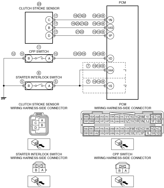
― Clutch stroke sensor terminal C—PCM terminal 1N
― Clutch stroke sensor terminal B—PCM terminal 1AS
― Clutch stroke sensor terminal D—PCM terminal 1P
• Is there continuity?
|
Yes
|
Go to the next step.
|
|
No
|
Repair or replace the wiring harness for a possible open circuit, then go to Step 24.
|
|
23
|
INSPECT CLUTCH STROKE SENSOR
• Inspect the clutch stroke sensor.
• Is there any malfunction?
|
Yes
|
Replace the clutch stroke sensor, then go to the next step.
|
|
No
|
Repeat Step 4.
|
|
24
|
VERIFY DTC TROUBLESHOOTING COMPLETED
• Make sure to reconnect all disconnected connectors.
• Clear the DTC from the PCM memory using the M-MDS.
• Perform the KOEO or KOER self test.
• Is the same DTC present?
|
Yes
|
Repeat the inspection from Step 1.
• If the malfunction recurs, replace the PCM.
Go to the next step.
|
|
No
|
Go to the next step.
|
|
25
|
VERIFY AFTER REPAIR PROCEDURE
• Perform the “AFTER REPAIR PROCEDURE”.
• Are any DTCs present?
|
Yes
|
Go to the applicable DTC inspection.
|
|
No
|
DTC troubleshooting completed.
|