|
1
|
VERIFY RELATED SERVICE INFORMATION AVAILABILITY
• Verify related Service Information availability.
• Is any related Service Information available?
|
Yes
|
Perform repair or diagnosis according to the available Service Information.
• If the vehicle is not repaired, go to the next step.
|
|
No
|
Go to the next step.
|
|
2
|
INSPECT BATTERY
• Switch the ignition to off.
• Is there any malfunction?
|
Yes
|
Recharge or replace the battery, then go to Step 7.
|
|
No
|
Go to the next step.
|
|
3
|
INSPECT POOR INSTALLATION NUT OF GENERATOR TERMINAL B
• Switch the ignition to off.
• Inspect the generator terminal B installation nut for looseness.
• Is the nut loose?
|
Yes
|
Retighten the generator terminal B installation nut, then go to Step 7.
|
|
No
|
Go to the next step.
|
|
4
|
INSPECT POOR INSTALLATION OF BATTERY POSITIVE TERMINAL
• Inspect the battery positive terminal for looseness.
• Is the terminal loose?
|
Yes
|
Connect the battery positive terminal correctly, then go to Step 7.
|
|
No
|
Go to the next step.
|
|
5
|
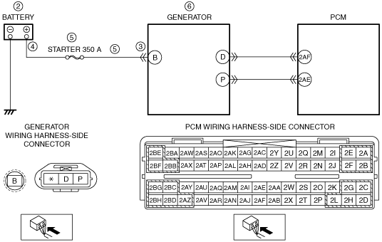
INSPECT BATTERY CHARGING CIRCUIT FOR OPEN CIRCUIT OR SHORT TO GROUND
• Disconnect the generator terminal B.
• Measure the voltage between generator terminal B (wiring harness-side) and body ground.
• Is the voltage B+?
|
Yes
|
Go to the next step.
|
|
No
|
Inspect the STARTER 350 A fuse.
• If the fuse is melt:
-
― Repair or replace the wiring harness for a possible short to ground.
― Replace the fuse.
• If the fuse is deterioration:
-
― Replace the fuse.
• If the fuse is normal:
-
― Repair or replace the wiring harness for a possible open circuit.
Go to Step 7.
|
|
6
|
INSPECT GENERATOR
• Is there any malfunction?
|
Yes
|
Repair or replace the malfunctioning part according to the inspection results, then go to the next step.
|
|
No
|
Go to the next step.
|
|
7
|
VERIFY DTC TROUBLESHOOTING COMPLETED
• Make sure to reconnect all disconnected connectors.
• Clear the DTC from the PCM memory using the M-MDS.
• Perform the KOER self test.
• Is the same DTC present?
|
Yes
|
Repeat the inspection from Step 1.
• If the malfunction recurs, replace the PCM.
Go to the next step.
|
|
No
|
Go to the next step.
|
|
8
|
VERIFY AFTER REPAIR PROCEDURE
• Perform the “AFTER REPAIR PROCEDURE”.
• Are any DTCs present?
|
Yes
|
Go to the applicable DTC inspection.
|
|
No
|
DTC troubleshooting completed.
|