 |
am3zzw00006280
VARIABLE VALVE TIMING ACTUATOR REMOVAL/INSTALLATION [MZR 1.5, MZR 1.6]
id0110s1803700
1. Remove the battery cover. (See BATTERY REMOVAL/INSTALLATION [MZR 1.5, MZR 1.6].)
2. Disconnect the negative battery cable.
3. Perform the following procedure.
4. Remove the ignition coils. (See IGNITION COIL REMOVAL/INSTALLATION [MZR 1.5, MZR 1.6].)
5. Set the wiring harness out of the way.
6. Remove the cylinder head cover. (See TIMING CHAIN REMOVAL/INSTALLATION [MZR 1.5, MZR 1.6].)
7. Remove the aerodynamic under cover No.2 and splash shield as a single unit. (See AERODYNAMIC UNDER COVER NO.2 REMOVAL/INSTALLATION.) (See SPLASH SHIELD REMOVAL/INSTALLATION.)
8. Remove the drive belt. (See DRIVE BELT REMOVAL/INSTALLATION [MZR 1.5, MZR 1.6].)
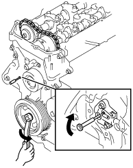
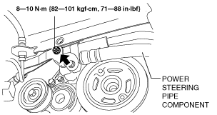
9. Remove the nut shown in the figure and set the power steering pipe component out of the way.
am3zzw00006280
|
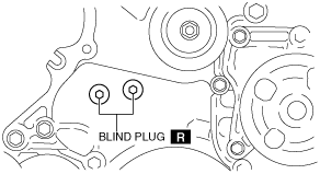
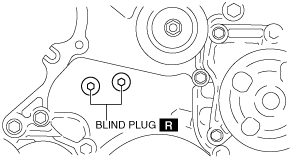
10. Remove the engine front cover blind plug as shown in the figure.
am3zzw00006281
|
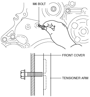
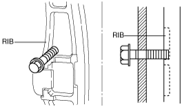
11. Insert a M6 bolt (45 to 80 mm length bolt with threads to the end) into the right-side service hole shown in the figure, and set the bolt at a slightly outward position by loosening it approx. 2 mm from where it contacts the tensioner arm.
am3zzw00006282
|
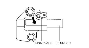
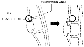
12. Release tension on the timing chain.
am3zzw00006283
|
am3zzw00006284
|
am2zzw00000095
|
am3zzw00006285
|
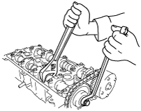
13. Fix the camshaft using a wrench on the cast hexagon. Remove the camshaft sprocket installation bolt.
am2zzw00001662
|
14. Remove the timing sprocket on the exhaust side with the timing chain positioned out of the way.
am2zzw00000100
|
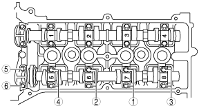
15. Loosen the camshaft cap installation bolts in two or three steps in the order shown in the figure, and remove the camshaft caps.
am3zzw00008106
|
16. Remove the intake camshaft and variable valve timing actuator as a single unit.
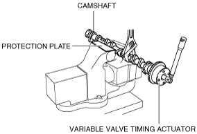
17. Lock the camshaft against rotation by holding the camshaft with the vise and securing the cast hexagon with a wrench.
am3zzw00006292
|
18. Loosen the variable valve timing actuator installation bolt, and then remove the variable valve timing actuator.
19. Install the variable valve timing actuator.
20. Tighten the variable valve timing actuator installation bolt.
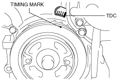
21. Align the timing marks on the crank pulley and the front cover, and then align the No.1 cylinder to the TDC.
am3zzw00008107
|
22. With No.1 cylinder cam aligned at TDC of the compression stroke, install the variable valve timing actuator and the camshaft on the intake air side as a single unit.
23. Install the camshaft caps to the position of a carved seal number to shown in the figure, and tighten the camshaft installation bolts in two or three steps uniformly in the order shown in the figure.
am3zzw00008108
|
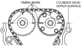
24. Align the sprocket timing marks on the intake and exhaust camshafts so that they form a straight line in alignment with the upper horizontal surface of the cylinder head.
am3zzw00008109
|
25. Fix the camshaft using a wrench on the cast hexagon. Install the camshaft sprocket installation bolt.
26. Remove the M6 bolt holding the tensioner arm.
27. Verify that there is no slack in the timing chain, and then verify that the marks on the camshaft sprocket and the crank pulley are aligned.
28. Inspect the valve timing by rotating the crankshaft clockwise twice.
29. Install the new engine front cover blind plug.
am3zzw00008110
|
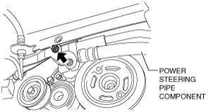
30. Install the nut shown in the figure.
am3zzw00008111
|
31. Install the drive belt. (See DRIVE BELT REMOVAL/INSTALLATION [MZR 1.5, MZR 1.6].)
32. Install the aerodynamic under cover No.2 and splash shield as a single unit. (See AERODYNAMIC UNDER COVER NO.2 REMOVAL/INSTALLATION.) (See SPLASH SHIELD REMOVAL/INSTALLATION.)
33. Install the cylinder head cover. (See TIMING CHAIN REMOVAL/INSTALLATION [MZR 1.5, MZR 1.6].)
34. Install the wiring harness.
35. Install the ignition coils. (See IGNITION COIL REMOVAL/INSTALLATION [MZR 1.5, MZR 1.6].)
36. Install the fresh-air duct and the air cleaner as a single unit. (See INTAKE-AIR SYSTEM REMOVAL/INSTALLATION [MZR 1.5, MZR 1.6].)
37. Connect the negative battery cable. (See BATTERY REMOVAL/INSTALLATION [MZR 1.5, MZR 1.6].)
38. Install the battery cover. (See BATTERY REMOVAL/INSTALLATION [MZR 1.5, MZR 1.6].)