CRANKSHAFT POSITION (CKP) SENSOR REMOVAL/INSTALLATION [MZR 2.3 DISI Turbo]
id0140e5800600
Removal
-
Caution
-
• When foreign material, such as an iron chips, gets on the CKP sensor, it can cause abnormal output from the sensor because of flux turbulence and adversely affect engine control. Be sure there is no foreign material on the CKP sensor when replacing.
• Do not assemble the CKP sensor or change the installation position using any method other than the following. Otherwise, it could negatively affect engine controls, such as the ignition timing and fuel injection.
1. Remove the battery cover. (See BATTERY REMOVAL/INSTALLATION [MZR 2.3 DISI Turbo].)
2. Disconnect the negative battery cable. (See BATTERY REMOVAL/INSTALLATION [MZR 2.3 DISI Turbo].)
3. Perform the following procedure for easier access.
- (1) Remove the aerodynamic under cover No.2. (See AERODYNAMIC UNDER COVER NO.2 REMOVAL/INSTALLATION.)
- (2) Remove the front splash shield (RH). (See SPLASH SHIELD REMOVAL/INSTALLATION.)
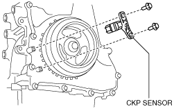
4. Disconnect the CKP sensor connector.
5. Remove the CKP sensor.
Installation
-
Caution
-
• When foreign material, such as an iron chips, gets on the CKP sensor, it can cause abnormal output from the sensor because of flux turbulence and adversely affect engine control. Be sure there is no foreign material on the CKP sensor when replacing.
• Do not assemble the CKP sensor or change the installation position using any method other than the following. Otherwise, it could negatively affect engine controls, such as the ignition timing and fuel injection.
1. Perform the following procedure so that piston No.1 is at the TDC.
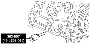
- (1) Rotate the crankshaft in the direction of the engine rotation and remove the cylinder block lower blind plug when the No. 1 cylinder is at the point prior to TDC of compression, then install the SST.
-
- (2) Rotate the crankshaft in the direction of the engine rotation so that the No.1 piston is at TDC of the compression stroke. (Until the crank weight contacts SST and stops.)
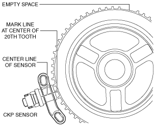
2. Using a straight edge, draw a straight line directly in the center of the twentieth tooth of the crankshaft pulley pulse wheel (counting counterclockwise from the empty space).
-
Caution
-
• If the line is not accurately drawn, ignition timing, fuel injection and other engine control systems will be adversely effected. Draw the straight line carefully using a straight edge.
3. Align the center line of the CKP sensor and the line drawn in Step 2, then install the sensor.
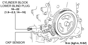
4. Install the CKP sensor fitting bolts.
5. Remove the SST then install the cylinder block lower blind plug.