 |
am3zzw00004909
STEERING WHEEL AND COLUMN REMOVAL/INSTALLATION [WITHOUT ADVANCED KEYLESS ENTRY AND PUSH BUTTON START SYSTEM]
id0614008004h1
1. Remove the dashboard under cover (if equipped).
2. Remove the driver-side front scuff plate. (See FRONT SCUFF PLATE REMOVAL/INSTALLATION.)
3. Remove the driver-side front side trim. (See FRONT SIDE TRIM REMOVAL/INSTALLATION.)
4. Remove the bonnet release lever. (See BONNET LATCH AND RELEASE LEVER REMOVAL/INSTALLATION.)
5. Remove the upper panel. (See UPPER PANEL REMOVAL/INSTALLATION.)
6. Remove the shift knob (MTX). (See MANUAL TRANSAXLE SHIFT MECHANISM REMOVAL/INSTALLATION.)
7. Remove the selector lever knob (ATX). (See AUTOMATIC TRANSAXLE SHIFT MECHANISM REMOVAL/INSTALLATION.)
8. Remove the shift panel. (See SHIFT PANEL REMOVAL/INSTALLATION.)
9. Remove the side wall. (See SIDE WALL REMOVAL/INSTALLATION.)
10. Remove the console. (See CONSOLE REMOVAL/INSTALLATION.)
11. Remove the lower panel. (See LOWER PANEL REMOVAL/INSTALLATION.)
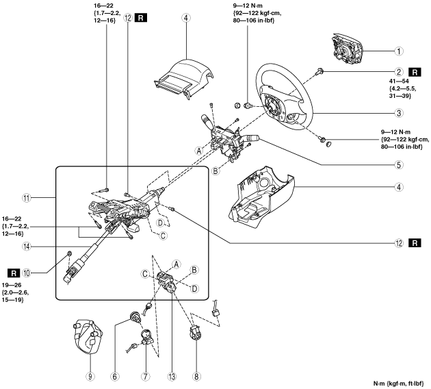
12. Remove in the order indicated in the table.
13. Install in the reverse order of removal.
am3zzw00004909
|
|
1
|
Driver-side air bag module
|
|
2
|
Lockbolt
|
|
3
|
Steering wheel
(See Steering Wheel Removal Note.)
|
|
4
|
Column cover
|
|
5
|
Clock spring, combination switch
|
|
6
|
Key cylinder
(See Key Cylinder Removal Note.)
|
|
7
|
Coil antenna
|
|
8
|
Ignition switch
|
|
9
|
Joint cover
|
|
10
|
Joint bolt
(See Joint Bolt Installation Note.)
|
|
11
|
Steering shaft component
|
|
12
|
Steering lock mounting bolt
|
|
13
|
Steering lock
|
|
14
|
Steering shaft
|
Steering Wheel Removal Note
1. Set the wheels in the straight-ahead position.
2. Remove the steering wheel using any commercially available puller.
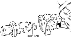
Key Cylinder Removal Note
1. Insert the key into the key cylinder and turn it to the ACC position.
2. Insert a pin from the position indicated by the arrow in the figure, and while pressing the lock bar with the pin, remove the key cylinder from the steering lock component.
am3uuw00004638
|
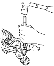
Steering Lock Mounting Bolt, Steering Lock Removal Note
1. Make a groove in the heads of the steering lock mounting bolts using a chisel and hammer.
am3uuw00004639
|
2. Remove the steering lock.
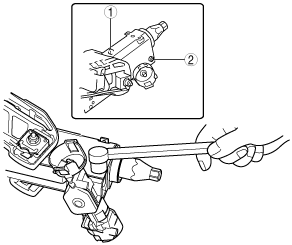
Steering Lock, Steering Lock Mounting Bolt Installation Note
1. Assemble area A of the steering lock to area B of the steering shaft, and press the steering lock in the direction of the arrow in the figure until it contacts the steering shaft.
am3uuw00006905
|
2. Temporarily install the steering lock to the steering shaft using a new steering lock mounting bolt.
3. Tighten the steering lock mounting bolts in the order shown in the figure until the heads break off.
am3uuw00006906
|
Steering Shaft Component Installation Note
1. Verify that the adjusting lever is in the LOCK position.
2. Tighten the bolts in alphabetical order.
am3uuw00002362
|
Joint Bolt Installation Note
1. Install the steering shaft component to the steering gear.
2. After temporarily install the joint bolt to the intermediate shaft joint, verify that the joint bolt is installed to the groove of the steering gear.
am3uuw00002157
|
3. Tighten the joint bolt to the specified torque.
Key Cylinder Installation Note
1. Insert the key into the key cylinder and turn it to the ACC position.
2. Install the key cylinder to the steering lock.
Steering Wheel Installation Note
1. Set the wheels in the straight-ahead position and install the steering wheel.