|
am3zzw00012350
CONTROLLER AREA NETWORK (CAN) MALFUNCTION DIAGNOSIS FLOW [MULTIPLEX COMMUNICATION SYSTEM (L.H.D. (EXCEPT MZR-CD 2.2, MZR 2.0 DISI i-stop))]
id0902k4005600
CAN malfunction diagnosis flow
Flowchart
am3zzw00012350
|
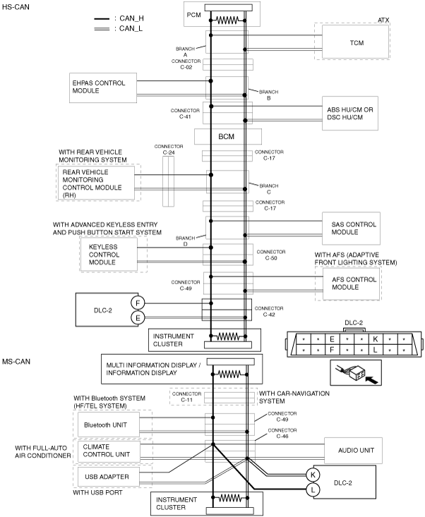
System wiring diagram
am3zzw00010565
|
Diagnostic procedure
|
Step |
Inspection |
Action |
|
|---|---|---|---|
|
1
|
INSPECT IF COMMUNICATION BETWEEN M-MDS AND PCM IS POSSIBLE
• Connect the M-MDS (IDS) to the DLC-2.
• Switch the ignition ON.
• Perform vehicle identification.
• Can the vehicle be identified?
|
Yes
|
Go to the next step.
|
|
No
|
Go to Step 5 as a malfunction in the HS-CAN circuit has occurred.
|
||
|
2
|
INSPECT MODULE FOR INABILITY TO COMMUNICATE DUE TO CAN MALFUNCTION
• Implement the network test using the M-MDS (IDS).
• Is there a module indicating a malfunction?
|
Yes
|
Go to Step 14 as a malfunction in the CAN circuit has occurred.
|
|
No
|
Go to the next step.
|
||
|
3
|
INSPECT FOR SHORT TO POWER SUPPLY IN HS-CAN OR CAN_H SIDE OF MS-CAN
• Measure the voltage between the following terminals:
• Is B+ voltage measured between any of the terminals?
|
Yes
|
A short to power supply in the HS-CAN or the CAN_H side of the MS-CAN has occurred.
Determine the location of the short to power supply according to the diagnosis procedure for determining the location of a short to power supply.
|
|
No
|
Go to the next step.
|
||
|
4
|
INSPECT FOR SHORT TO GROUND IN CAN_L SIDE OF HS-CAN OR MS-CAN
• Measure the voltage between the following terminals:
• Is the voltage measured as 0 V?
|
Yes
|
A short to ground on the CAN_L side of the HS-CAN or MS-CAN has occurred.
Determine the location of the short to ground according to the diagnosis procedure for determining the location of a short to ground.
|
|
No
|
The current CAN circuit is normal, return to FOREWARD, and go to the next step of the CAN malfunction diagnosis in the troubleshooting procedure.
|
||
|
5
|
VERIFY IF VEHICLE UNDER DIAGNOSIS IS EQUIPPED WITH ADVANCED PUSH START SYSTEM.
• Is the vehicle equipped with the advanced push start system?
|
Yes
|
Go to the next step.
|
|
No
|
Go to Step 7.
|
||
|
6
|
VERIFY IF ADVANCED PUSH START SYSTEM HAS MALFUNCTION
• Switch the ignition ON.
• Can the ignition be switched ON?
|
Yes
|
Go to the next step.
|
|
No
|
A malfunction in the advanced push start system has occurred.
Perform diagnosis according to the symptom troubleshooting.
|
||
|
7
|
INSPECT FOR MALFUNCTION IN M-MDS
• Connect the M-MDS (IDS) to a normal vehicle and implement vehicle identification.
• Can the vehicle be identified?
|
Yes
|
Go to the next step.
|
|
No
|
A malfunction in the M-MDS (IDS) can be considered.
Repair the M-MDS (IDS).
|
||
|
8
|
INSPECT HS-CAN CIRCUIT FOR SHORT TO POWER SUPPLY
• Measure the voltage between the following terminals:
• Is B+ voltage measured between any of the terminals?
|
Yes
|
A short to power supply in the CAN_H side or CAN_L of HS-CAN has occurred.
Determine the location of the short to power supply according to the diagnosis procedure for determining the location of a short to power supply.
|
|
No
|
Go to the next step.
|
||
|
9
|
INSPECT HS-CAN CIRCUIT FOR OPEN CIRCUIT
• Measure the voltage between the following terminals:
• Is the voltage between both terminals (CAN_H side and CAN_L side) equal?
|
Yes
|
Go to Step 13 as a short to ground or a short between circuits has occurred in the HS-CAN.
|
|
No
|
Go to the next step.
|
||
|
10
|
VERIFY IF VEHICLE UNDER DIAGNOSIS IS EQUIPPED WITH IMMOBILIZER SYSTEM
• Is the vehicle equipped with the immobilizer system?
|
Yes
|
Go to the next step.
|
|
No
|
Go to Step 12.
|
||
|
11
|
DETERMINE IF OPEN CIRCUIT LOCATION IN HS-CAN CIRCUIT IS BETWEEN DLC AND BRANCH E OR ELSEWHERE
• Start the engine.
• Can the engine be started?
|
Yes
|
Go to Step 12.
|
|
No
|
An open circuit has occurred between the PCM and branch E in the HS-CAN.
Determine the location of the open circuit according to the diagnosis procedure for determining the location of an open circuit.
|
||
|
12
|
DETERMINE IF OPEN CIRCUIT LOCATION IN HS-CAN CIRCUIT IS BETWEEN DLC AND BRANCH E OR ELSEWHERE
• Switch the ignition ON.
• Verify if the check engine light in the instrument cluster illuminates.
• Start the engine.
• Verify if the check engine light turns off.
• Does the check engine light turn off?
|
Yes
|
An open circuit between DLC-2 and branch E has occurred.
Repair or replace the wiring harness for an open circuit, then return to Step 1.
|
|
No
|
An open circuit has occurred between the PCM and branch E in the HS-CAN.
Determine the location of the open circuit according to the diagnosis procedure for determining the location of an open circuit.
|
||
|
13
|
VERIFY MALFUNCTION OCCURED IN HS-CAN CIRCUIT
• Measure the voltage between the following terminals:
• Is the voltage between both terminals (CAN_H side and CAN_L side) 0 V?
|
Yes
|
A short to ground in CAN_H side of HS-CAN has occurred.
Determine the location of the short to ground according to the diagnosis procedure for determining the location of a short to ground.
|
|
No
|
A short between circuits in the CAN_H side and the CAN_L side of HS-CAN has occurred.
Determine the location of the short between circuits according to the diagnosis procedure for determining the location of a short between circuits.
|
||
|
14
|
DETERMINE CAN COMMUNICATION SPECIFICATION IN WHICH MALFUNCTION OCCURS
• Refer to the CAN communication specification quick reference table and verify the CAN communication specification (HS-CAN or MS-CAN) that is connected to the module which is indicating a malfunction.
• Is the module that is indicating a malfunction HS-CAN?
|
Yes
|
An open circuit in the HS-CAN has occurred.
Determine the location of the open circuit according to the diagnosis procedure for determining the location of an open circuit.
|
|
No
|
Go to the next step.
|
||
|
15
|
INSPECT FOR SHORT TO POWER SUPPLY IN CAN_L SIDE OF MS-CAN
• Measure voltage between DLC-2 terminal K (CAN_L side) and body ground.
• Can B+ voltage be measured?
|
Yes
|
A short to power supply in the CAN_L side of the MS-CAN has occurred.
Determine the location of the short to power supply according to the diagnosis procedure for determining the location of a short to power supply.
|
|
No
|
Go to the next step.
|
||
|
16
|
INSPECT FOR OPEN CIRCUIT IN MS-CAN
• Measure the voltage between the following terminals:
• Is the voltage between both terminals (CAN_H side and CAN_L side) equal?
|
Yes
|
Go to the next step.
|
|
No
|
Open circuit in MS-CAN has occurred.
Determine the location of the open circuit according to the diagnosis procedure for determining the location of an open circuit.
|
||
|
17
|
VERIFY MALFUNCTION OCCURRED IN MS-CAN
• Measure the voltage between the following terminals:
• Is the voltage between both terminals (CAN_H side and CAN_L side) equal?
|
Yes
|
A short to ground in the CAN_H side of the MS-CAN has occurred.
Determine the location of the short to ground according to the diagnosis procedure for determining the location of a short to ground.
|
|
No
|
A short between circuits on the CAN_H side and CAN_L side of MS-CAN has occurred.
Determine the location of the short between circuits according to the diagnosis procedure for determining the location of a short between circuits.
|
||
CAN communication specification quick reference table
|
CAN communication related module (M-MDS display) |
CAN communication specification |
|
|---|---|---|
|
HS-CAN |
MS-CAN |
|
|
PCM (PCM)
|
×
|
|
|
TCM (TCM)
|
×
|
|
|
EHPAS control module (EPS)
|
×
|
|
|
DSC HU/CM (ABS) (with DSC)
|
×
|
|
|
ABS HU/CM (ABS) (with ABS)
|
×
|
|
|
BCM (BCM)
|
×
|
|
|
Rear vehicle monitoring control module (RH) (RVM)
|
×
|
|
|
SAS control module (RCM)
|
×
|
|
|
Keyless control module (RKE)
|
×
|
|
|
AFS control module (AFS)
|
×
|
|
|
Instrument cluster (IC)
|
×
|
|
|
Multi information display/information display (MID)
|
|
×
|
|
Bluetooth unit
|
|
×
|
|
Climate control unit (EATC)
|
|
×
|
|
Audio unit (ACU)
|
|
×
|
HS-CAN signal waveform
|
CAN circuit condition |
CAN communication specification |
Special Features |
Signal waveform (reference) |
|---|---|---|---|
|
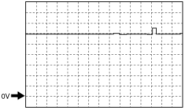
Normal
|
CAN_H
|
-
|
 |
|
• Connection terminal: DLC-2: terminal F (+) ↔ body ground ( -)
• Oscilloscope setting: 0.5 V/DIV (Y), 200 µs/DIV (X), DC range
|
|||
|
CAN_L
|
-
|
 |
|
|
• Connection terminal: DLC-2: terminal E (+) ↔ Body ground ( - )
• Oscilloscope setting: 0.5 V/DIV (Y), 200 µs/DIV (X), DC range
|
|||
|
Short to power supply on CAN_H side
|
CAN_H
|
• B+ constant voltage.
|
 |
|
• Connection terminal: DLC-2: terminal F (+) ↔ Body ground ( - )
• Oscilloscope setting: 2 V/DIV (Y), 2 ms/DIV (X), DC range
|
|||
|
CAN_L
|
• Waveform with maximum voltage at B+.
|
 |
|
|
• Connection terminal: DLC-2: terminal E (+) ↔ Body ground ( - )
• Oscilloscope setting: 2 V/DIV (Y), 2 ms/DIV (X), DC range
|
|||
|
Short to power supply on CAN_L side
|
CAN_H
|
• B+ constant voltage.
|
 |
|
CAN_L
|
• CAN_H side: DLC-2: terminal F (+) ↔ Body ground ( - )
• CAN_L side: DLC-2: terminal E (+) ↔ Body ground ( - )
• 2 V/DIV (Y), 5 ms/DIV (X), DC range
|
||
|
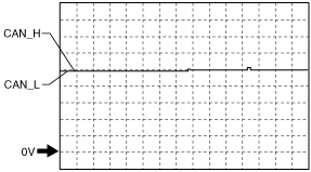
Short to ground on CAN_H side
|
CAN_H
|
CAN_H side, CAN_L side: 0 V constant voltage.
|
 |
|
CAN_L
|
• CAN_H side: DLC-2: terminal F (+) ↔ Body ground ( - )
• CAN_L side: DLC-2: terminal E (+) ↔ Body ground ( - )
• 0.5 V/DIV (Y), 5 ms/DIV (X), DC range
|
||
|
Short to ground on CAN_L side
|
CAN_H
|
Waveform with the minimum voltage at 0 V.
|
 |
|
• CAN_H side: DLC-2: terminal F (+) ↔ Body ground ( - )
• 0.5 V/DIV (Y), 5 ms/DIV (X), DC range
|
|||
|
CAN_L
|
Voltage is 0 V.
|
 |
|
|
• CAN_L side: DLC-2: terminal E (+) ↔ Body ground ( - )
• 0.5 V/DIV (Y), 5 ms/DIV (X), DC range
|
|||
|
Short between circuits
|
CAN_H
|
CAN_H side, CAN_L side: Approx. 2.5 V constant voltage
|
 |
|
CAN_L
|
• CAN_H side: DLC-2: terminal F (+) ↔ Body ground ( - )
• CAN_L side: DLC-2: terminal E (+) ↔ Body ground ( - )
• 0.5 V/DIV (Y), 5 ms/DIV (X), DC range
|
||
|
Open circuit on CAN_H side
(Open circuit between PCM and instrument cluster)
|
CAN_H
|
• As indicated by a, a waveform which is the same as the signal waveform on the CAN_L side may display.
• The maximum voltage is higher than normal.
|
 |
|
• Connection terminal: DLC-2: terminal F (+) ↔ Body ground ( - )
• Oscilloscope setting: 0.5 V/DIV (Y), 200 µs/DIV (X), DC range
|
|||
|
CAN_L
|
The minimum voltage is lower than normal.
|
 |
|
|
• Connection terminal: DLC-2: terminal E (+) ↔ Body ground ( - )
• Oscilloscope setting: 0.5 V/DIV (Y), 200 µs/DIV (X), DC range
|
|||
|
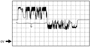
Open circuit on CAN_L side
(Open circuit between PCM and instrument cluster)
|
CAN_H
|
Maximum voltage is higher than normal.
|
 |
|
• CAN_H side: DLC-2: terminal F (+) ↔ Body ground ( - )
• 0.5 V/DIV (Y), 200 µs/DIV (X), DC range
|
|||
|
CAN_L
|
As indicated by b, a waveform which is the same as the signal waveform on the CAN_H side may display.
|
 |
|
|
• CAN_L side: DLC-2: terminal E (+) ↔ Body ground ( - )
• 0.5 V/DIV (Y), 200 µs/DIV (X), DC range
|
|||
|
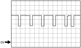
Open circuit on CAN_H side
(Open circuit other than between PCM and instrument cluster)
|
CAN_H
|
• Minimum voltage is the same as the minimum voltage on the CAN_L side.
• It shows a waveform with a constant voltage range and cycle as indicated by c.
|
 |
|
• Connection terminal: DLC-2: terminal F (+) ↔ Body ground ( - )
• Oscilloscope setting: 0.5 V/DIV (Y), 200 µs/DIV (X), DC range
|
|||
|
CAN_L
|
• Minimum voltage is lower than normal.
• It shows a waveform with a constant voltage range and cycle as indicated by c.
|
 |
|
|
• Connection terminal: DLC-2: terminal E (+) ↔ Body ground ( - )
• Oscilloscope setting: 0.5 V/DIV (Y), 200 µs/DIV (X), DC range
|
|||
|
Open circuit on CAN_L side
(Open circuit other than between PCM and instrument cluster)
|
CAN_H
|
• Maximum voltage is higher than normal.
• It shows a waveform with a constant voltage range and cycle as indicated by c.
|
 |
|
• CAN_H side: DLC-2: terminal F (+) ↔ Body ground ( - )
• 0.5 V/DIV (Y), 200 µs/DIV (X), DC range
|
|||
|
CAN_L
|
• The maximum voltage is the same as the maximum voltage on the CAN_H side.
• It shows a waveform with a constant voltage range and cycle as indicated by c.
|
 |
|
|
• CAN_L side: DLC-2: terminal E (+) ↔ Body ground ( - )
• 0.5 V/DIV (Y), 200 µs/DIV (X), DC range
|
MS-CAN signal waveform
|
CAN circuit condition |
CAN communication specification |
Special Features |
Signal waveform (reference) |
|---|---|---|---|
|
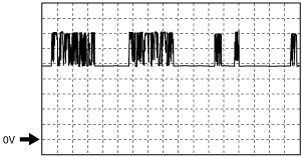
Normal
|
CAN_H
|
-
|
 |
|
• Connection terminal: DLC-2: terminal L (+) ↔ Body ground ( - )
• Oscilloscope setting: 0.5 V/DIV (Y), 1 ms/DIV (X), DC range
|
|||
|
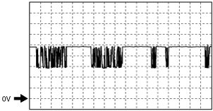
CAN_L
|
-
|
 |
|
|
• Connection terminal: DLC-2: terminal K (+) ↔ Body ground ( - )
• Oscilloscope setting: 0.5 V/DIV (Y), 1 ms/DIV (X), DC range
|
|||
|
Short to power supply on CAN_H side
|
CAN_H
|
• B+ constant voltage.
|
|
|
• Connection terminal: DLC-2: terminal L (+) ↔ Body ground ( - )
• Oscilloscope setting: 2 V/DIV (Y), 2 ms/DIV (X), DC range
|
|||
|
CAN_L
|
• Waveform with maximum voltage at B+.
|
|
|
|
• Connection terminal: DLC-2: terminal K (+) ↔ Body ground ( - )
• Oscilloscope setting: 2 V/DIV (Y), 2 ms/DIV (X), DC range
|
|||
|
Short to power supply on CAN_L side
|
CAN_H
|
• B+ constant voltage.
|
|
|
CAN_L
|
• CAN_H side: DLC-2: terminal L (+) ↔ Body ground ( - )
• CAN_L side: DLC-2: terminal K (+) ↔ Body ground ( - )
• 2 V/DIV (Y), 5 ms/DIV (X), DC range
|
||
|
Short to ground on CAN_H side
|
CAN_H
|
CAN_H side, CAN_L side: 0 V constant voltage.
|
|
|
CAN_L
|
• CAN_H side: DLC-2: terminal L (+) ↔ Body ground ( - )
• CAN_L side: DLC-2: terminal K (+) ↔ Body ground ( - )
• 0.5 V/DIV (Y), 5 ms/DIV (X), DC range
|
||
|
Short to ground on CAN_L side
|
CAN_H
|
Waveform with the minimum voltage at 0 V.
|
|
|
• CAN_H side: DLC-2: terminal L (+) ↔ Body ground ( - )
• 0.5 V/DIV (Y), 5 ms/DIV (X), DC range
|
|||
|
CAN_L
|
Voltage is 0 V.
|
|
|
|
• CAN_L side: DLC-2: terminal K (+) ↔ Body ground ( - )
• 0.5 V/DIV (Y), 5 ms/DIV (X), DC range
|
|||
|
Short between circuits
|
CAN_H
|
CAN_H side, CAN_L side: Approx. 2.5 V constant voltage.
|
|
|
CAN_L
|
• CAN_H side: DLC-2: terminal L (+) ↔ Body ground ( - )
• CAN_L side: DLC-2: terminal K (+) ↔ Body ground ( - )
• 0.5 V/DIV (Y), 5 ms/DIV (X), DC range
|
||
|
Open circuit on CAN_H side
(Open circuit between multi information display/information display and instrument cluster)
|
CAN_H
|
• As indicated by d, a waveform which is the same as the signal waveform on the CAN_L side may display.
• Maximum voltage is higher than normal.
|
 |
|
• Connection terminal: DLC-2: terminal F (+) ↔ Body ground ( - )
• Oscilloscope setting: 0.5 V/DIV (Y), 1 ms/DIV (X), DC range
|
|||
|
CAN_L
|
Minimum voltage is lower than normal.
|
 |
|
|
• Connection terminal: DLC-2: terminal E (+) ↔ Body ground ( - )
• Oscilloscope setting: 0.5 V/DIV (Y), 1 ms/DIV (X), DC range
|
|||
|
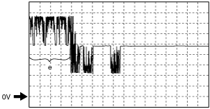
Open circuit on CAN_L side
(Open circuit between multi information display/information display and instrument cluster)
|
CAN_H
|
Maximum voltage is higher than normal.
|
 |
|
• CAN_H side: DLC-2: terminal F (+) ↔ Body ground ( - )
• 0.5 V/DIV (Y), 1 ms/DIV (X), DC range
|
|||
|
CAN_L
|
• Minimum voltage is lower than normal.
• As indicated by e, a waveform which is the same as the signal waveform on the CAN_H side may display.
|
 |
|
|
• CAN_L side: DLC-2: terminal E (+) ↔ Body ground ( - )
• 0.5 V/DIV (Y), 2 ms/DIV (X), DC range
|
|||
|
Open circuit on CAN_H side
(Open circuit other than between multi information display/information display and instrument cluster)
|
CAN_H
|
• Minimum voltage is the same as the minimum voltage on the CAN_L side.
• It shows a waveform with a constant voltage range and cycle as indicated by f.
|
 |
|
• Connection terminal: DLC-2: terminal F (+) ↔ Body ground ( - )
• Oscilloscope setting: 0.5 V/DIV (Y), 1 ms/DIV (X), DC range
|
|||
|
CAN_L
|
• Minimum voltage is lower than normal.
• It shows a waveform with a constant voltage range and cycle as indicated by f.
|
 |
|
|
• Connection terminal: DLC-2: terminal E (+) ↔ Body ground ( - )
• Oscilloscope setting: 0.5 V/DIV (Y), 1 ms/DIV (X), DC range
|
|||
|
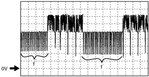
Open circuit on CAN_L side
(Open circuit other than between multi information display/information display and instrument cluster)
|
CAN_H
|
• Maximum voltage is higher than normal.
• It shows a waveform with a constant voltage range and cycle as indicated by f.
|
 |
|
• CAN_H side: DLC-2: terminal F (+) ↔ Body ground ( - )
• 0.5 V/DIV (Y), 1 ms/DIV (X), DC range
|
|||
|
CAN_L
|
• Maximum voltage is the same as the maximum voltage on the CAN_H side.
• It shows a waveform with a constant voltage range and cycle as indicated by f.
|
 |
|
|
• CAN_L side: DLC-2: terminal E (+) ↔ Body ground ( - )
• 0.5 V/DIV (Y), 1 ms/DIV (X), DC range
|