|
1
|
CONFIRM BCM DTC
• Perform the BCM DTC inspection using the M-MDS.
• Are the following DTCs present?
-
― B11C0:13
― B11C1:13
― B1175:13
― B1176:13
― B1178:11
|
Yes
|
Conduct a check according to the DTC.
|
|
No
|
Go to the next step.
|
|
2
|
INSPECT POWER SUPPLY FUSE
• Is the keyless receiver power supply fuse normal?
|
Yes
|
Go to the next step.
|
|
No
|
Inspect and repair short to GND in wiring harness at keyless receiver power supply circuit install an appropriate amperage fuse, then go to step 7.
|
|
3
|
INSPECT IF MALFUNCTION IS IN WIRING HARNESS (NO CONTINUITY BETWEEN FUSE BLOCK AND KEYLESS RECEIVER) OR ELSEWHERE
• Measure the voltage at the following keyless receiver terminal:
-
― B+ signal (terminal A)
• Is the voltage B+?
|
Yes
|
Go to the next step.
|
|
No
|
Repair the wiring harness between the fuse block and keyless receiver, then go to Step 7.
|
|
4
|
INSPECT IF MALFUNCTION IS IN WIRING HARNESS (NO CONTINUITY BETWEEN KEYLESS RECEIVER AND GROUND) OR ELSEWHERE
• Is there continuity between keyless receiver terminal E and ground?
|
Yes
|
Go to the next step.
|
|
No
|
Repair the wiring harness between the keyless receiver and ground, then go to Step 7.
|
|
5
|
INSPECT IF MALFUNCTION IS IN WIRING HARNESS (NO CONTINUITY BETWEEN KEYLESS RECEIVER AND BCM) OR ELSEWHERE
• Disconnect the keyless receiver connector and BCM connector.
• Is there continuity between the following terminals?
-
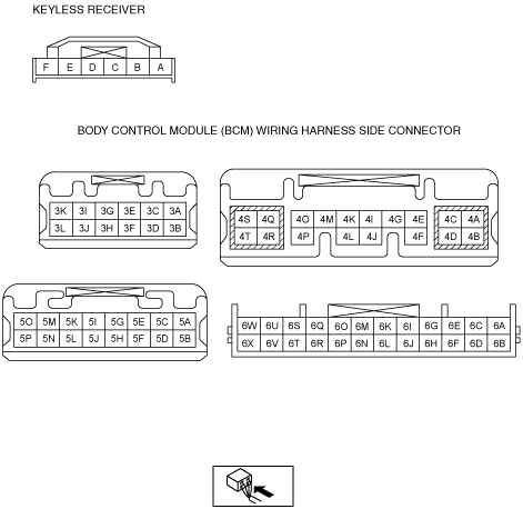
― 4K (BCM connector)—D (keyless receiver connector)
|
Yes
|
Go to the next step.
|
|
No
|
Repair the wiring harness between the keyless receiver and BCM, then go to Step 7.
|
|
6
|
INSPECT IF MALFUNCTION IS IN KEYLESS RECEIVER OR BCM
• Measure the signal wave pattern for BCM terminal 4K using an oscilloscope when the transmitter is operated with the key not inserted into the ignition key cylinder.
• Does the wave pattern change when the transmitter is operated?
-
Note
-
• Perform the oscilloscope setting using 0.5V/DIV (Y), 100ms/DIV (X), DC range.
|
Yes
|
Replace the BCM, then go to the next step.
|
|
No
|
Replace the keyless receiver, then go to the next step.
|
|
7
|
REINSPECT MALFUNCTION SYMPTOM AFTER REPAIR
• Does the keyless entry system operate properly?
|
Yes
|
Troubleshooting completed.
Explain repairs to the customer.
|
|
No
|
Reinspect the malfunction symptoms, then repeat from Step 1 if the malfunction recurs.
|