|
am3zzw00005271
THEFT-DETERRENT SIREN AND TILT SENSOR INSPECTION
id091400517100
4SD
1. Remove the following parts:
2. Remove the theft-deterrent siren with the connector connected.
3. Measure the theft-deterrent siren terminal voltage using the short wiring harness connector in the position shown in the figure.
am3zzw00005271
|
Terminal Voltage Table (Reference)
am3zzw00006840
|
|
Terminal |
Signal name |
Connected to |
Measurement condition |
Voltage (V) |
Inspection item(s) |
|---|---|---|---|---|---|
|
A
|
Power supply
|
BCM
|
Under any condition
|
B+
|
BCM
|
|
B
|
DATA
|
BCM
|
Terminal used for communication therefore determination based on terminal voltage inspection not possible.
|
||
|
D
|
Ground
|
Body ground
|
Under any condition
|
1.0 or less
|
Ground
|
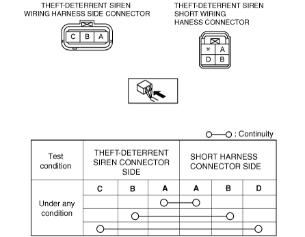
Continuity Inspection Of Short Wiring Harness Connector
1. Verify that the continuity between the short wiring harness connector terminals is as indicated in the table.
am3zzw00006841
|
5HB
1. Remove the following parts:
2. Remove the theft-deterrent siren with the connector connected.
3. Measure the theft-deterrent siren terminal voltage using the short wiring harness connector in the position shown in the figure.
am3zzw00005272
|
Terminal Voltage Table (Reference)
am3zzw00006840
|
|
Terminal |
Signal name |
Connected to |
Measurement condition |
Voltage (V) |
Inspection item(s) |
|---|---|---|---|---|---|
|
A
|
Power supply
|
BCM
|
Under any condition
|
B+
|
BCM
|
|
B
|
DATA
|
BCM
|
Terminal used for communication therefore determination based on terminal voltage inspection not possible.
|
||
|
D
|
Ground
|
Body ground
|
Under any condition
|
1.0 or less
|
Ground
|
Continuity Inspection Of Short Wiring Harness Connector
1. Verify that the continuity between the short wiring harness connector terminals is as indicated in the table.
am3zzw00006841
|