FRONT FOG LIGHT AIMING
id091800802200
-
Note
-
• If the following servicing is done, perform the front fog light aiming adjustment.
-
― Front fog light replacement
― Suspension replacement and removal/installation, servicing requiring vehicle height to be changed
• When using an aiming tester to input the inclination angle (tilt angle) of the optical axis, input 1.5% for the inclination angle.
1. Empty the vehicle except for the spare tire, jack and vehicle tools.
2. Adjust the tire pressure to the specification. (See WHEEL AND TIRE SPECIFICATION.)
3. Move the vehicle to level ground.
4. Sit on the driver-side seat alone.
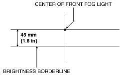
5. Make an adjustment-use screen as shown in the figure using double-weight, white paper. (Common to both left and right)
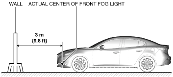
6. Line up the vehicle with the wall so that the distance to the front fog lights is 3 m {9.8 ft} from the wall.
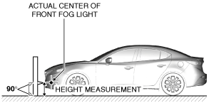
7. Measure the height at the center point of the front fog lights.
-
Note
-
• Measure the height at the center point of the front fog light in which the aiming is being adjusted because the vehicle height differs depending on vehicle conditions.
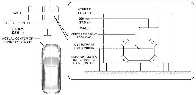
8. Align the center point of the front fog light with the center of the adjustment-use screen.
9. Set a partition in front of the front fog light which is not being adjusted to block the light.
10. Start the engine and charge the battery.
11. Turn on the front fog lights.
12. Verify that the actual brightness borderline of the fog light is at the brightness borderline position indicated by the adjustment-use screen.
-
• If the actual brightness borderline is not in the position indicated on the adjustment-use screen, perform the following adjustment:
- (1) Disconnect the negative battery cable. (See NEGATIVE BATTERY CABLE DISCONNECTION/CONNECTION [MZR 1.6].) (See NEGATIVE BATTERY CABLE DISCONNECTION/CONNECTION [SKYACTIV-G 1.5, SKYACTIV-G 2.0, SKYACTIV-G 2.5].) (See NEGATIVE BATTERY CABLE DISCONNECTION/CONNECTION [SKYACTIV-D 2.2].)(See NEGATIVE BATTERY CABLE DISCONNECTION/CONNECTION [SKYACTIV-D 1.5].)
-
- (2) Partially peel back the front mudguard. (See MUDGUARD REMOVAL/INSTALLATION.)
-
- (3) Remove the front fog light bezel No.1. (See FRONT FOG LIGHT BEZEL REMOVAL/INSTALLATION.)
-
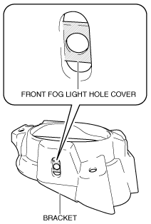
- (4) Remove the front fog light and the bracket before cutting the front fog light hole cover located on the bolt installation hole. (See FRONT FOG LIGHT REMOVAL/INSTALLATION.)
-
- (5) Cutout the hatch-marked area of the front fog light hole cover shown in the figure.
-
-
Note
-
• Remove all the shaded area shown in the figure so that the front fog light hole cover does not interfere with the bolt.
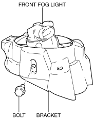
- (6) Install the front fog light to the bracket and temporarily tighten the bolt.
-
- (7) Install the front fog light and the bracket to the front bumper. (See FRONT FOG LIGHT REMOVAL/INSTALLATION.)
-
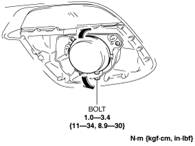
- (8) Move the front fog light in the direction of the arrow shown in the figure and adjust the brightness borderline.
-
- (9) Tighten the bolt.
-
- (10) Assemble the front fog light completely. (See FRONT FOG LIGHT REMOVAL/INSTALLATION.)
-
- (11) Install the front fog light bezel No.1. (See FRONT FOG LIGHT BEZEL REMOVAL/INSTALLATION.)
-
- (12) Install the front mudguard. (See MUDGUARD REMOVAL/INSTALLATION.)
-
- (13) Connect the negative battery cable. (See NEGATIVE BATTERY CABLE DISCONNECTION/CONNECTION [MZR 1.6].) (See NEGATIVE BATTERY CABLE DISCONNECTION/CONNECTION [SKYACTIV-G 1.5, SKYACTIV-G 2.0, SKYACTIV-G 2.5].) (See NEGATIVE BATTERY CABLE DISCONNECTION/CONNECTION [SKYACTIV-D 2.2].)(See NEGATIVE BATTERY CABLE DISCONNECTION/CONNECTION [SKYACTIV-D 1.5].)
-