Diagnostic procedure
|
STEP
|
INSPECTION
|
ACTION
|
|
|---|---|---|---|
|
1
|
VERIFY FREEZE FRAME DATA HAS BEEN RECORDED
• Has FREEZE FRAME DATA been recorded?
|
Yes
|
Go to the next step.
|
|
No
|
Record the FREEZE FRAME DATA on the repair order, then go to the next step.
|
||
|
2
|
VERIFY RELATED REPAIR INFORMATION AVAILABILITY
• Verify related service repair information availability.
• Is any related repair information available?
|
Yes
|
Perform repair or diagnosis according to the available repair information.
• If the vehicle is not repaired, go to the next step.
|
|
No
|
Go to the next step.
|
||
|
3
|
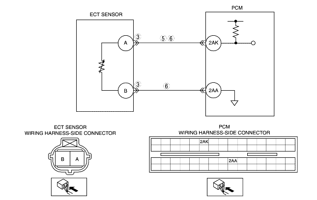
INSPECT TERMINAL BENT
• Turn the ignition switch off.
• Disconnect the ECT sensor connector.
• Inspect for bent of ECT sensor terminals A and B (part-side).
• Is there any malfunction?
|
Yes
|
Repair or replace the terminal, then go to Step 7.
|
|
No
|
Go to the next step.
|
||
|
4
|
CLASSIFY ECT SENSOR MALFUNCTION OR WIRING HARNESS MALFUNCTION
• Connect the WDS or equivalent to DLC-2.
• Access ECT PID.
• Verify ECT value when disconnecting ECT sensor connector.
• Does the ECT value change?
|
Yes
|
Replace the ECT sensor, then go to Step 7.
|
|
No
|
Go to the next step.
|
||
|
5
|
INSPECT ECT SIGNAL CIRCUIT FOR SHORT TO GROUND
• Turn the ignition switch off.
• Inspect continuity between ECT sensor terminal A (wiring harness-side) and body ground.
• Is there continuity?
|
Yes
|
Repair or replace the wiring harness for short to ground, then go to Step 7.
|
|
No
|
Go to the next step.
|
||
|
6
|
INSPECT IAT CIRCUIT FOR SHORT WIRING HARNESSES
• Inspect for continuity between ECT sensor terminal A and B (wiring harness-side).
• Is there continuity?
|
Yes
|
Repair or replace the wiring harness for short, then go to the next step.
|
|
No
|
Go to the next step.
|
||
|
7
|
VERIFY TROUBLESHOOTING OF DTC P0117 COMPLETED
• Make sure to reconnect all disconnected connectors.
• Clear the DTC from the PCM memory using the WDS or equivalent.
• Start the engine.
• Is the same DTC present?
|
Yes
|
Replace the PCM, then go to the next step.
|
|
No
|
Go to the next step.
|
||
|
8
|
VERIFY AFTER REPAIR PROCEDURE
• Perform the "After Repair Procedure".
• Are any DTC present?
|
Yes
|
Go to the applicable DTC troubleshooting.
(See DTC TABLE [LF, L3].)
|
|
No
|
Troubleshooting completed.
|
||