FUEL TANK REMOVAL/INSTALLATION
id011400801600
-
Warning
-
• Repairing a fuel tank containing fuel is dangerous. Explosion or fire may cause death or serious injury. Always properly steam clean a fuel tank before repairing it.
1. Park the vehicle on a level surface.
2. Follow "BEFORE SERVICE PRECAUTION" before performing any work operations to prevent fuel from spilling from the fuel system. (See BEFORE SERVICE PRECAUTION.)
-
Warning
-
• A person charged with static electricity could cause a fire or explosion, resulting in death or serious injury. Before draining fuel, make sure to discharge static electricity by touching a vehicle.
3. Drain the fuel from the fuel tank using the following procedure:
-
(1) Disconnect the quick release connector (in the engine compartment). (See QUICK RELEASE CONNECTOR REMOVAL/INSTALLATION.)
-
(2) Attach a long hose to the disconnected fuel pipe and drain the fuel into a proper receptacle.
-
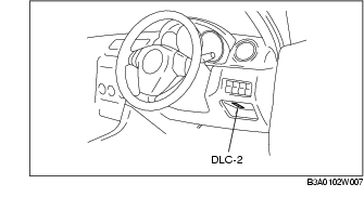
(3) Connect the WDS or equivalent to the DLC-2.
-
(4) Turn the ignition switch to the ON position.
-
(5) Using the simulation function "FP", start the fuel pump.
-
Caution
-
• The fuel pump may malfunction if it is operated without any fuel in the fuel tank (fuel pump idling). Constantly monitor the amount of fuel being discharged and immediately stop operation of the pump when essentially no fuel is being discharged.
-
(6) When essentially no fuel is being discharged from the hose, turn the ignition switch to the LOCK position.
-
(7) Disconnect the negative battery cable.
4. Remove the rear seat cushion. (See REAR SEAT REMOVAL/INSTALLATION.)
5. Remove the service hole cover.
6. Disconnect the fuel pump unit connector.
7. Remove the charcoal canister protector. (See CHARCOAL CANISTER REMOVAL/INSTALLATION.)
8. Lower the main silencer so that the insulator can be removed. (See EXHAUST SYSTEM REMOVAL/INSTALLATION [ZY, Z6].) (See EXHAUST SYSTEM REMOVAL/INSTALLATION [LF, L3].)
9. Remove the rear under cover (LH).
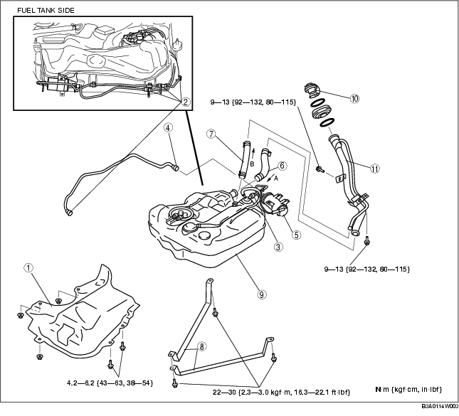
10. Remove in the order indicated in the table.
11. Install in the reverse order of removal.
12. Inspect all parts by performing "AFTER SERVICE PRECAUTION". (See AFTER SERVICE PRECAUTION.)
.
|
1
|
Insulator
|
|
2
|
Quick release connector (fuel tank front, fuel tank side)
|
|
3
|
Quick release connector (on rollover valve)
|
|
4
|
Quick release connector (on charcoal canister, purge solenoid valve side)
|
|
5
|
Charcoal canister
|
|
6
|
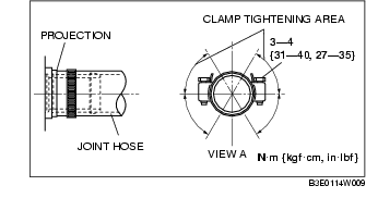
Joint hose
|
|
7
|
Breather hose
|
|
8
|
Strap
|
|
9
|
Fuel tank
|
|
10
|
Fuel-filler cap
|
|
11
|
Fuel-filler pipe
|
Fuel-filler Pipe Removal Note
1. Remove the rear tire (RH).
2. Remove the rear mudguard (RH).
3. Support the rear crossmember using a transmission jack.
4. Remove the rear shock absorber (RH) lower bolts. (See REAR SHOCK ABSORBER REMOVAL/INSTALLATION.)
5. Removal the three rear crossmember installation bolts (RH). (See REAR CROSSMEMBER REMOVAL/INSTALLATION.)
6. Loosen the three rear crossmember installation bolts (LH) about 10 mm {0.39 in}. (See REAR CROSSMEMBER REMOVAL/INSTALLATION.)
7. Lower the rear crossmember about 35-40 mm {1.4-1.5 in} using a transmission jack.
-
Note
-
• Because the rear crossmember is equipped with the positioning pins, rear wheel alignment inspection/adjustment is not necessary.
8. Remove the fuel-filler pipe.
Joint Hose Installation Note
1. Install the joint hose and clamp as shown in the figure.
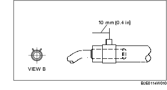
Breather Hose Installation Note
1. Install the breather hose and clamp as shown in the figure.