 |
am3zzw00009282
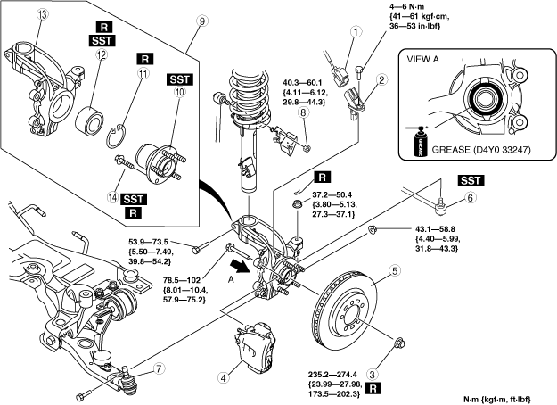
WHEEL HUB, STEERING KNUCKLE REMOVAL/INSTALLATION [LOCKNUT TYPE]
id0311008004a1
1. Remove in the order indicated in the table.
2. Install in the reverse order of removal.
3. After installation, inspect the front wheel alignment and adjust it if necessary. (See FRONT WHEEL ALIGNMENT.)
am3zzw00009282
|
|
1
|
ABS wheel-speed sensor connector
|
|
2
|
ABS wheel-speed sensor
|
|
3
|
Locknut
(See Locknut Installation Note.)
(See Locknut Installation Note.)
|
|
4
|
Brake caliper component
|
|
5
|
Disc plate
|
|
6
|
Tie-rod end ball joint
|
|
7
|
Front lower arm ball joint
|
|
8
|
Stabilizer control link upper nut
|
|
9
|
Wheel hub, steering knuckle component
|
|
10
|
Wheel hub component
|
|
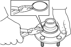
11
|
Retaining clip
|
|
12
|
Wheel bearing
(See Wheel Bearing Removal Note.)
|
|
13
|
Steering knuckle
|
|
14
|
Hub bolt
(See Wheel Hub Bolt Removal Note.)
|
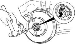
Locknut Removal Note
1. Knock the crimped portion of the locknut outward using a small chisel and a hummer.
am3zzw00009283
|
2. Lock the hub by applying the brakes.
3. Remove the locknut.
Wheel Hub Component Removal Note
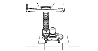
1. Remove the wheel hub component using the SSTs.
am3zzw00009284
|
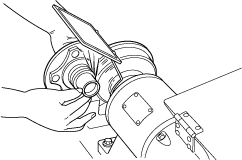
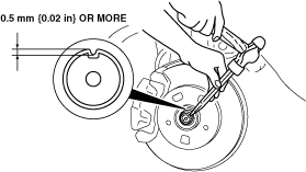
2. If the bearing inner race remains on the front wheel hub component, perform the following procedure:
Without using SST
1. Grind a section of the bearing inner race until approx. 0.5 mm {0.02 in} remains.
am3zzw00009285
|
2. Remove the bearing inner race using a chisel.
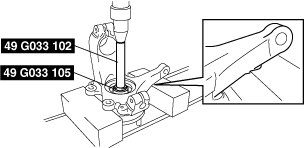
With using SST
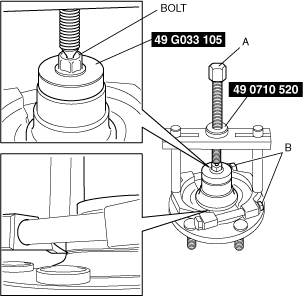
1. Remove the part as shown in the figure.
am3zzw00009286
|
2. Position the SSTs and a spare bolt (M10 length 90 mm {3.5 in} or less) as shown in the figure.
am3zzw00009287
|
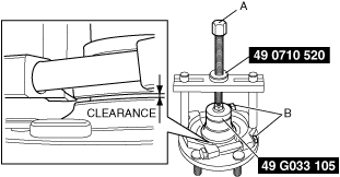
3. Tighten SST section A until the space between the bearing inner race and wheel hub component is 1—2 mm {0.04—0.07 in}.
am3zzw00009288
|
4. Temporarily loosen SST section A and position the SST again.
5. Tighten SST section A and remove the bearing inner race.
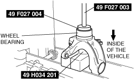
Wheel Bearing Removal Note
1. Remove the wheel bearing using the SSTs.
am3zzw00009289
|
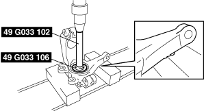
Wheel Hub Bolt Removal Note
1. Remove the hub bolt using a press.
am3zzw00009290
|
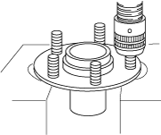
Wheel Hub Bolt Installation Note
1. Install the new hub bolt using a press.
am3zzw00009291
|
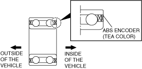
Wheel Bearing Installation Note
am3zzw00009292
|
1. Install the new wheel bearing using the SSTs.
am3zzw00009293
|
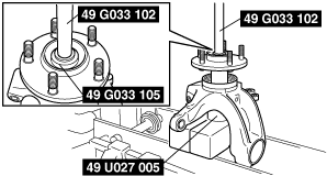
Wheel Hub Component Installation Note
1. Install the wheel hub component so that there is no clearance between the wheel hub and bearing using the SSTs.
am3zzw00009294
|
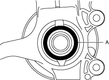
Wheel Hub, Steering Knuckle Component Installation Note
1. Apply grease (D4Y0 33247) to the wheel bearing inner race and drive shaft contact surface (Area A in figure).
am3zzw00009295
|
2. Install the wheel hub, steering knuckle component.
Locknut Installation Note
1. Install a new locknut and stake it as shown.
am3zzw00009296
|