 |
g3e313zw9s01
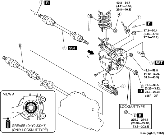
DRIVE SHAFT REMOVAL/INSTALLATION
id031300801900
1. Drain the transaxle oil. (See TRANSAXLE OIL REPLACEMENT [F35M-R].) (See TRANSAXLE OIL REPLACEMENT [G35M-R].) (See AUTOMATIC TRANSAXLE FLUID (ATF) REPLACEMENT.)
2. Remove in the order indicated in the table.
3. Install in the reverse order of removal.
g3e313zw9s01
|
|
1
|
ABS wheel-speed sensor connector
|
|
2
|
Lockbolt or Locknut
|
|
3
|
Tie-rod end ball joint
|
|
4
|
Stabilizer control link upper nut
|
|
5
|
Front lower arm ball joint
|
|
6
|
Drive shaft
(See Drive Shaft Removal Note.)
|
|
7
|
Clip
(See Clip Installation Note.)
|
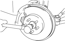
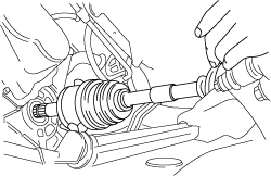
Drive Shaft Removal Note
1. Install a spare bolt onto the drive shaft.
2. Tap the bolt with a copper hammer and separate the drive shaft from the axle.
am3zzw00038257
|
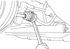
3. Separate the drive shaft from the wheel hub.
4. Separate the drive shaft (LH) from the transaxle by prying with a bar inserted between the outer ring and the transaxle.
am3zzw00038258
|
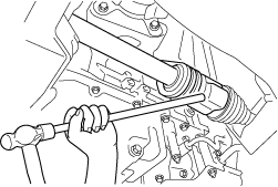
5. Disconnect the drive shaft (RH) from the joint shaft by tapping the transaxle side outer ring with a brass bar and hammer.
am3zzw00038259
|
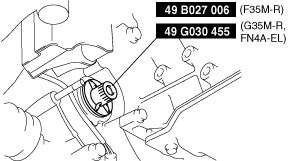
6. Install the SSTs to the transaxle after the drive shaft is removed.
am3zzw00038260
|
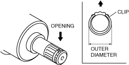
Clip Installation Note
1. Install a new drive shaft clip to the clip groove at the end of the drive shaft with the clip opening facing upward and the clip width within the specification.
am3zzw00038261
|
2. After installation, measure the outer diameter.
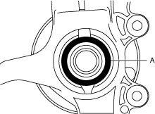
Drive Shaft Installation Note
Left side
1. Apply grease (D4Y0 33247) to the wheel bearing inner race and drive shaft contact surface (Area A in figure). (Only locknut type)
am3zzw00038262
|
2. Insert the drive shaft into the wheel hub.
3. Apply transaxle oil to the oil seal lip.
4. Install the drive shaft to the transaxle.
am3zzw00038263
|
5. After installation, pull the transaxle side outer ring forward to confirm that the drive shaft is securely held by the clip.
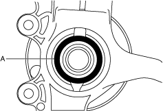
Right side
1. Install a new clip onto the joint shaft. (See JOINT SHAFT REMOVAL/INSTALLATION.)
2. Apply grease (D4Y0 33247) to the wheel bearing inner race and drive shaft contact surface (Area A in figure). (Only locknut type)
am3zzw00038264
|
3. Insert the drive shaft to the wheel hub.
4. Insert the drive shaft to the joint shaft.
5. After installation, pull the transaxle side outer ring forward to confirm that the drive shaft is securely held by the clip.