Diagnostic procedure
|
STEP
|
INSPECTION
|
ACTION
|
|
|---|---|---|---|
|
1
|
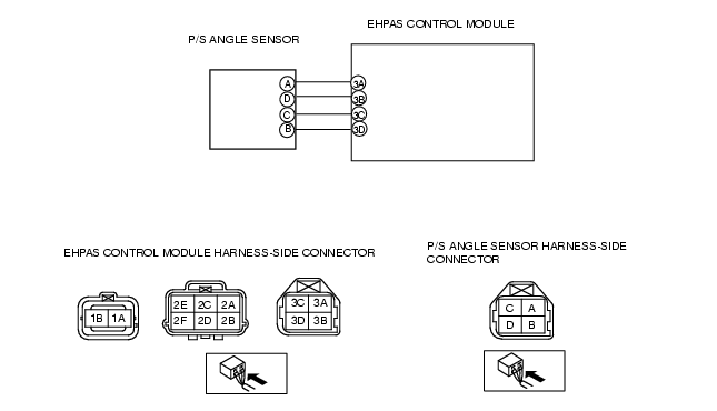
INSPECT POWER SUPPLY VOLTAGE OF P/S ANGLE SENSOR
• Turn the ignition switch to the ON position (Engine off).
• Measure the voltage between P/S angle sensor terminal C and ground.
• Is the voltage 4.5-5.5 V?
|
Yes
|
Go to the next step.
|
|
No
|
Repair or replace the wiring harness between EHPAS control module terminal 3C and P/S angle sensor terminal C, then go to the step 7.
|
||
|
2
|
INSPECT GROUND CIRCUIT OF P/S ANGLE SENSOR FOR OPEN CIRCUIT
• Turn the ignition switch off.
• Disconnect the EHPAS control module and P/S angle sensor connectors.
• Inspect for continuity between EHPAS control module terminal 3A and P/S angle sensor terminal A.
• Is there continuity?
|
Yes
|
Go to the next step.
|
|
No
|
Repair or replace the wiring harness between EHPAS control module terminal 3A and P/S angle sensor terminal A, then go to the step 7.
|
||
|
3
|
INSPECT P/S ANGLE SENSOR SIGNAL CIRCUIT FOR SHORT TO POWER
• Turn ignition key to ON (engine OFF).
• Measure the voltage between the EHPAS control module and body ground at the following:
• Is voltage B+?
|
Yes
|
Repair or replace the related wiring harnesses between the EHPAS control module and P/S angle sensor, then go to the step 7.
|
|
No
|
Go to next step.
|
||
|
4
|
INSPECT P/S ANGLE SENSOR SIGNAL CIRCUIT FOR SHORT TO GROUND
• Turn the ignition switch off.
• Inspect continuity between the EHPAS control module and body ground at the following:
• Is there continuity?
|
Yes
|
Repair or replace the related wiring harnesses between the EHPAS control module and P/S angle sensor, then go to the step 7.
|
|
No
|
Go to the next step.
|
||
|
5
|
INSPECT SENSORS 1 AND 2 OF THE P/S ANGLE SENSOR FOR CONTINUITY
• Turn the ignition switch off.
• Disconnect the EHPAS control module and P/S angle sensor connectors.
• Inspect for continuity between P/S angle sensor terminals B and D.
• Is there continuity?
|
Yes
|
Replace the P/S angle sensor, then go to the step 7.
|
|
No
|
Go to the next step.
|
||
|
6
|
INSPECT PID FOR P/S ANGLE SENSOR RING MALFUNCTION USING WDS OR EQUIVALENT
• Turn the ignition switch off.
• Connect the WDS or equivalent to the DLC-2.
• Select the "STEER_RATE" PID.
• Verify that the WDS display changes correctly according to steering wheel operation.
• Does it change correctly?
|
Yes
|
Go to the next step.
|
|
No
|
Replace the P/S angle sensor ring (built into the steering gear valve housing), then go to the next step.
|
||
|
7
|
VERIFY THAT THE SAME DTC IS NOT PRESENT
• Reconnect all disconnected connectors.
• Clear the DTC from the memory.
(See Clearing DTCs Procedure.)
• Is the same DTC present?
|
Yes
|
• Repeat the inspection from Step 1.
• If the malfunction recurs, replace the electric power steering oil pump.
|
|
No
|
Go to the next step.
|
||
|
8
|
VERIFY THAT NO OTHER DTCS ARE PRESENT
• Are any other DTCs output?
|
Yes
|
Go to the applicable DTC inspection.
(See DTC Table.)
|
|
No
|
DTC troubleshooting completed.
|
||
Diagnostic procedure
|
STEP
|
INSPECTION
|
ACTION
|
|
|---|---|---|---|
|
1
|
INSPECT PID FOR STEERING ANGLE SENSOR MALFUNCTION USING WDS OR EQUIVALENT
• Turn the ignition switch off.
• Connect the WDS or equivalent to the DLC-2.
• Select the "STEER_RATE" PID.
• Verify that the WDS display changes correctly according to steering wheel operation.
• Does it change correctly?
|
Yes
|
Go to the next step.
|
|
No
|
Replace the steering angle sensor.
|
||
|
2
|
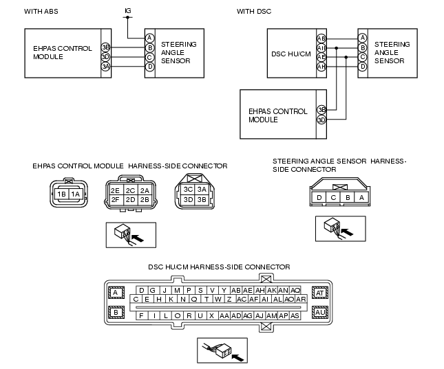
INSPECT POWER SUPPLY VOLTAGE OF STEERING ANGLE SENSOR
• Turn the ignition switch to the ON position (Engine off).
• Measure the voltage between steering angle sensor terminal A and ground.
• Is the voltage B+?
|
Yes
|
Go to the next step.
|
|
No
|
With ABS
• Repair or replace the wiring harness between ignition switch and steering angle sensor terminal A, then go to the step 7.
With DSC
• Repair or replace the wiring harness between DSC HU/CM terminal AB and steering angle sensor terminal A, then go to the step 7.
|
||
|
3
|
INSPECT GROUND CIRCUIT OF STEERING ANGLE SENSOR FOR OPEN CIRCUIT
• Turn the ignition switch off.
• Disconnect the EHPAS control module (with ABS) or DSC HU/CM (with DSC) and steering angle sensor connectors.
• Inspect for continuity between EHPAS control module terminal 3A (with ABS) or DSC HU/CM terminal AH (with DSC) and steering angle sensor terminal D.
• Is there continuity?
|
Yes
|
Go to the next step.
|
|
No
|
Repair or replace the wiring harness between EHPAS control module terminal 3A (with ABS) or DSC HU/CM terminal AH (with DSC) and steering angle sensor terminal D, then go to the step 7.
|
||
|
4
|
INSPECT STEERING ANGLE SENSOR SIGNAL CIRCUIT FOR SHORT TO POWER
• Turn ignition key to ON (engine OFF).
• Measure the voltage between the EHPAS control module and body ground at the following:
• Is voltage B+?
|
Yes
|
Repair or replace the related wiring harnesses between the EHPAS control module and steering angle sensor, then go to the step 7.
|
|
No
|
Go to next step.
|
||
|
5
|
INSPECT STEERING ANGLE SENSOR SIGNAL CIRCUIT FOR SHORT TO GROUND
• Turn the ignition switch off.
• Inspect continuity between the EHPAS control module and body ground at the following:
• Is there continuity?
|
Yes
|
Repair or replace the related wiring harnesses between the EHPAS control module and steering angle sensor, then go to the step 7.
|
|
No
|
Go to the next step.
|
||
|
6
|
INSPECT SENSORS 1 AND 2 OF THE STEERING ANGLE SENSOR FOR CONTINUITY
• Turn the ignition switch off.
• Disconnect the EHPAS control module and steering angle sensor connectors.
• Inspect for continuity between steering angle sensor terminals B and C.
• Is there continuity?
|
Yes
|
Replace the steering angle sensor, then go to the step 7.
|
|
No
|
Go to the next step.
|
||
|
7
|
VERIFY THAT THE SAME DTC IS NOT PRESENT
• Reconnect all disconnected connectors.
• Clear the DTC from the memory.
(See Clearing DTCs Procedure.)
• Is the same DTC present?
|
Yes
|
• Repeat the inspection from Step 1.
• If the malfunction recurs, replace the electric power steering oil pump.
|
|
No
|
Go to the next step.
|
||
|
8
|
VERIFY THAT NO OTHER DTCS ARE PRESENT
• Are any other DTCs output?
|
Yes
|
Go to the applicable DTC inspection.
(See DTC Table.)
|
|
No
|
DTC troubleshooting completed.
|
||