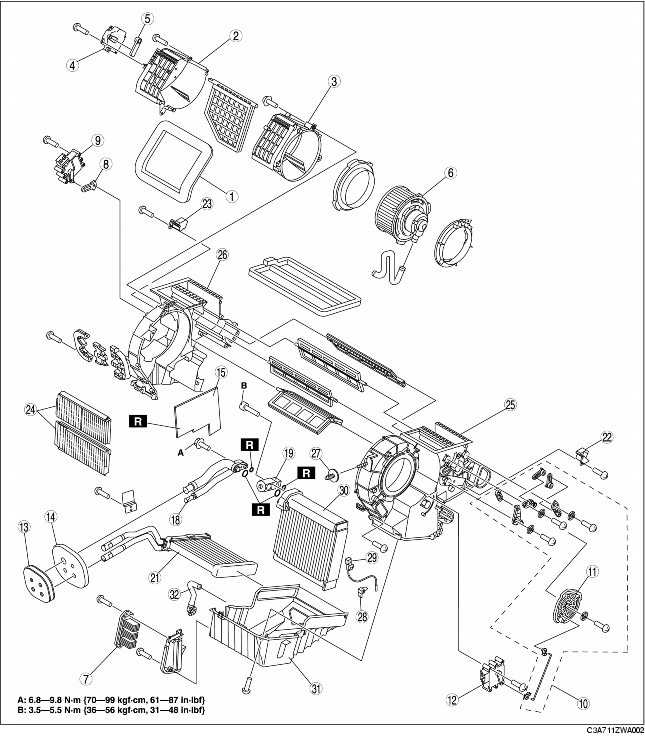
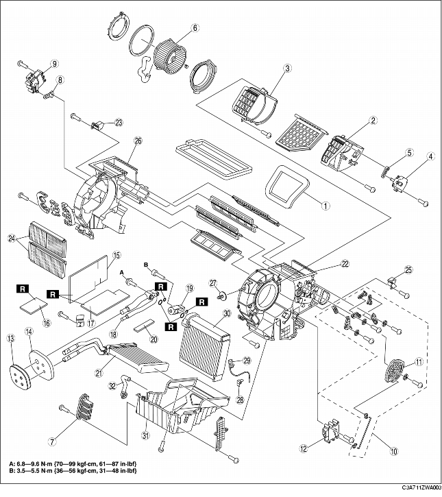
1. Disassemble in the order indicated in the table.
2. Assemble in the reverse order of disassembly.
L.H.D.
R.H.D.
.
|
1
|
Adhesive polyurethane (1)
|
|
2
|
Blower case (1)
|
|
3
|
Blower case (2)
|
|
4
|
Air intake actuator
|
|
5
|
Air intake link set
|
|
6
|
Blower motor
(See BLOWER MOTOR REMOVAL.)
(See BLOWER MOTOR INSTALLATION.)
|
|
7
|
Power MOS FET
|
|
8
|
Air mix link set
|
|
9
|
Air mix actuator
|
|
10
|
Airflow mode link set
|
|
11
|
Airflow mode main link
|
|
12
|
Airflow mode actuator
|
|
13
|
Polyurethane foam
|
|
14
|
Adhesive polyurethane (2)
|
|
15
|
Adhesive polyurethane (3)
|
|
16
|
Adhesive polyurethane (4) (R.H.D.)
|
|
17
|
Adhesive polyurethane (5) (R.H.D.)
|
|
18
|
Evaporator pipe
|
|
19
|
Expansion valve
|
|
20
|
Adhesive polyurethane (6) (R.H.D.)
|
|
21
|
Heater core
|
|
22
|
Bracket (1)
|
|
23
|
Bracket (2)
|
|
24
|
Air filter
|
|
25
|
A/C case (1)
|
|
26
|
A/C case (2)
|
|
27
|
Bolt
(See Bolt Assembly Note.)
|
|
28
|
Sensor clamp
(See Sensor Clamp Assembly Note.)
|
|
29
|
Evaporator temperature sensor
|
|
30
|
Evaporator
|
|
31
|
A/C case (3)
|
|
32
|
Drain hose
|
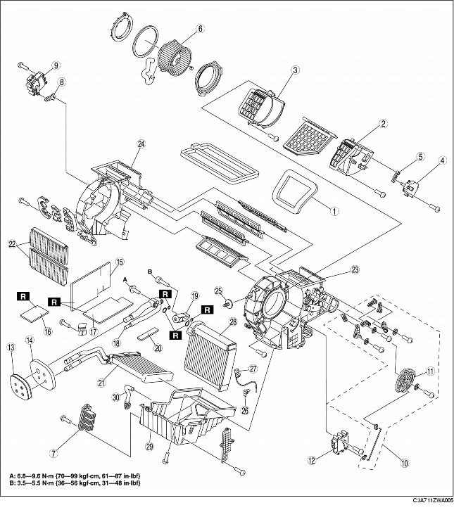
1. Disassemble in the order indicated in the table.
2. Assemble in the reverse order of disassembly.
L.H.D.

R.H.D.
.
|
1
|
Adhesive polyurethane (1)
|
|
2
|
Blower case (1)
|
|
3
|
Blower case (2)
|
|
4
|
Air intake actuator
|
|
5
|
Air intake link set
|
|
6
|
Blower motor
(See BLOWER MOTOR REMOVAL.)
(See BLOWER MOTOR INSTALLATION.)
|
|
7
|
Power MOS FET
|
|
8
|
Air mix link set
|
|
9
|
Air mix actuator
|
|
10
|
Airflow mode link set
|
|
11
|
Airflow mode main link
|
|
12
|
Airflow mode actuator
|
|
13
|
Polyurethane foam
|
|
14
|
Adhesive polyurethane (2)
|
|
15
|
Adhesive polyurethane (3)
|
|
16
|
Adhesive polyurethane (4) (R.H.D.)
|
|
17
|
Adhesive polyurethane (5) (R.H.D.)
|
|
18
|
Evaporator pipe
|
|
19
|
Expansion valve
|
|
20
|
Adhesive polyurethane (6) (R.H.D.)
|
|
21
|
Heater core
|
|
22
|
Air filter
|
|
23
|
A/C case (1)
|
|
24
|
A/C case (2)
|
|
25
|
Bolt
(See Bolt Assembly Note.)
|
|
26
|
Sensor clamp
(See Sensor Clamp Assembly Note.)
|
|
27
|
Evaporator temperature sensor
|
|
28
|
Evaporator
|
|
29
|
A/C case (3)
|
|
30
|
Drain hose
|
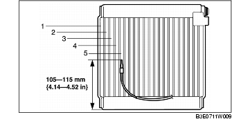
1. Assemble the evaporator temperature sensor as shown in the figure.
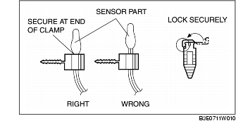
1. Attach the sensor clamp as shown in the figure.
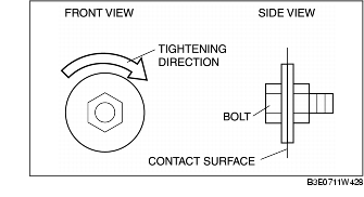
1. Tighten it to the right so that it is flush to the contact surface.