Diagnostic procedure
|
STEP
|
INSPECTION
|
ACTION
|
|
|---|---|---|---|
|
1
|
INSPECT DRIVER-SIDE AIR BAG MODULE (INFLATOR NO.2)
• Using the WDS or equivalent, verify the following PID/DATA monitor.
• Is the resistance of the driver-side air bag module normal?
|
Yes
|
Replace the SAS control module.
|
|
No
|
Go to the next step.
|
||
|
2
|
INSPECT DRIVER-SIDE AIR BAG MODULE CONNECTOR (CLOCK SPRING)
• Turn the ignition switch to the LOCK position.
• Disconnect the negative battery cable and wait for 1 min or more.
• Disconnect the driver-side air bag module connector.
• Is there any malfunction of the driver-side air bag module connector?
|
Yes
|
Replace the air bag wiring harness and /or clock spring.
|
|
No
|
Go to the next step.
|
||
|
3
|
VERIFY WHETHER MALFUNCTION IS IN DRIVER-SIDE AIR BAG MODULE (INFLATOR NO.2) OR RELATED WIRING HARNESS
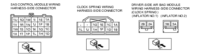
• Connect the leads of the SST (Fuel and thermometer checker) or apply 2-ohm resistance to driver-side air bag module (inflator No.1) connector terminals 2A and 2B, and driver-side air bag module (inflator No.2) connector terminals 3A and 3B.
• Set the resistance of the SST (Fuel and thermometer checker) to the 2-ohm position.
• Connect the negative battery cable.
• Turn the ignition switch to the ON position.
• Are DTCs B1058, B2228, B2230, B2232 and/or B2234 indicated?
|
Yes
|
Go to the next step.
|
|
No
|
Replace the driver-side air bag module.
|
||
|
4
|
INSPECT CLOCK SPRING
• Inspect the clock spring.
• Is the clock spring normal?
|
Yes
|
Go to the next step.
|
|
No
|
Replace the clock spring.
|
||
|
5
|
INSPECT WIRING HARNESS BETWEEN CLOCK SPRING AND SAS CONTROL MODULE
• Turn the ignition switch to the LOCK position.
• Disconnect the negative battery cable and wait for 1 min or more.
• Remove the column cover.
• Disconnect the clock spring connector.
• Remove the glove compartment.
• Disconnect the passenger-side air bag module connector.
• Disconnect the driver and passenger-side front seat connectors.
• Disconnect the driver and passenger-side curtain air bag module connectors.
• Remove the console.
• Disconnect the SAS control module connector.
• Inspect the wiring harness between SAS control module terminal 1Q and clock spring terminal 1H, SAS control module terminal 1U and clock spring terminal 1F for the following:
• Is the wiring harness normal?
|
Yes
|
Replace the SAS control module.
|
|
No
|
Replace the air bag wiring harness.
|
||