|
1
|
IDENTIFY TRIGGER DTC FOR FREEZE FRAME DATA (MODE 2)
• Perform the Freeze Frame PID Data Access Procedure.
• Is the DTC P0154:00 on FREEZE FRAME DATA (Mode 2)?
|
Yes
|
Go to the next step.
|
|
No
|
Go to the troubleshooting procedure for DTC on FREEZE FRAME DATA (Mode 2).
|
|
2
|
VERIFY FREEZE FRAME DATA (MODE 2)/SNAPSHOT DATA HAS BEEN RECORDED
• Has the FREEZE FRAME DATA (Mode 2)/snapshot data been recorded?
|
Yes
|
Go to the next step.
|
|
No
|
Record the FREEZE FRAME DATA (Mode 2)/snapshot data on the repair order, then go to the next step.
|
|
3
|
VERIFY RELATED SERVICE INFORMATION AVAILABILITY
• Verify related Service Information availability.
• Is any related Service Information available?
|
Yes
|
Perform repair or diagnosis according to the available Service Information.
• If the vehicle is not repaired, go to the next step.
|
|
No
|
Go to the next step.
|
|
4
|
INSPECT INSTALLATION OF A/F SENSOR
• Inspect if the A/F sensor is loosely installed.
• Is the A/F sensor installed securely?
|
Yes
|
Go to the next step.
|
|
No
|
Retighten the A/F sensor, then go to Step 10.
|
|
5
|
INSPECT SEALING OF ENGINE COOLANT PASSAGE
• Perform the “ENGINE COOLANT LEAKAGE INSPECTION”.
• Is there any malfunction?
|
Yes
|
Repair or replace the malfunctioning part according to the inspection results, then go to Step 10.
|
|
No
|
Go to the next step.
|
|
6
|
INSPECT GAS LEAKAGE FROM EXHAUST SYSTEM
• Visually inspect for the exhaust gas leakage between exhaust manifold and A/F sensor.
• Is there any leakage?
|
Yes
|
Repair or replace the malfunctioning part according to the inspection results, then go to Step 10.
|
|
No
|
Go to the next step.
|
|
7
|
INSPECT A/F SENSOR
• Inspect the A/F sensor.
• Is there any malfunction?
|
Yes
|
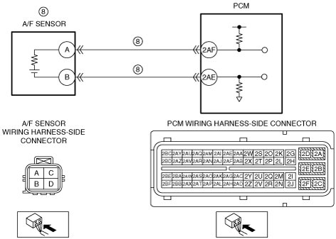
Inspect for short or open circuit between the following terminals (wiring harness-side):
• A/F sensor terminal A—PCM terminal 2AF
• A/F sensor terminal B—PCM terminal 2AE
-
― If there is any malfunction:
-
• Repair or replace the suspected wiring harness.
― If there is no malfunction:
-
• Replace the A/F sensor.
Go to Step 10.
|
|
No
|
Go to the next step.
|
|
8
|
INSPECT ENGINE COMPRESSION
• Inspect the engine compression.
• Is there any malfunction?
|
Yes
|
Overhaul the engine for repairs, then go to Step 10.
|
|
No
|
Go to the next step.
|
|
9
|
VERIFY WHETHER MALFUNCTION IS A/F SENSOR OR ELSEWHERE
• Make sure to reconnect all disconnected connectors.
• Clear the DTC from the PCM memory using the M-MDS.
• Perform the Repair Verification Drive Mode.
• Is the same DTC present?
|
Yes
|
Replace the A/F sensor, then go to the next step.
|
|
No
|
Go to the next step.
|
|
10
|
VERIFY DTC TROUBLESHOOTING COMPLETED
• Make sure to reconnect all disconnected connectors.
• Clear the DTC from the PCM memory using the M-MDS.
• Perform the Repair Verification Drive Mode.
• Is the same DTC present?
|
Yes
|
Replace the PCM, then go to the next step.
|
|
No
|
Go to the next step.
|
|
11
|
VERIFY AFTER REPAIR PROCEDURE
• Perform the “AFTER REPAIR PROCEDURE”.
• Are any DTCs present?
|
Yes
|
Go to the applicable DTC inspection.
|
|
No
|
DTC troubleshooting completed.
|