|
1
|
VERIFY FREEZE FRAME DATA (MODE 2)/SNAPSHOT DATA HAS BEEN RECORDED
• Has the FREEZE FRAME DATA (Mode 2)/snapshot data been recorded?
|
Yes
|
Go to the next step.
|
|
No
|
Record the FREEZE FRAME DATA (Mode 2)/snapshot data on the repair order, then go to the next step.
|
|
2
|
VERIFY RELATED SERVICE INFORMATION AVAILABILITY
• Verify related Service Information availability.
• Is any related Service Information available?
|
Yes
|
Perform repair or diagnosis according to the available Service Information.
• If the vehicle is not repaired, go to the next step.
|
|
No
|
Go to the next step.
|
|
3
|
INSPECT OCV CONNECTOR CONDITION
• Switch the ignition to off.
• Disconnect the OCV connector.
• Inspect for poor connection (such as damaged/pulled-out pins, corrosion).
• Is there any malfunction?
|
Yes
|
Repair or replace the connector and/or terminals, then go to Step 9.
|
|
No
|
Go to the next step.
|
|
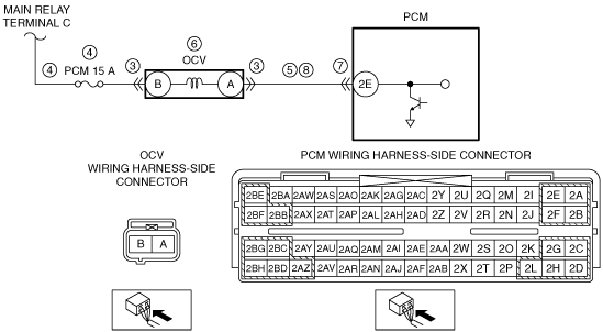
4
|
INSPECT OCV POWER SUPPLY CIRCUIT FOR SHORT TO GROUND OR OPEN CIRCUIT
• OCV connector is disconnected.
• Switch the ignition to ON (engine off).
• Measure the voltage at the OCV terminal B (wiring harness-side).
• Is the voltage B+?
|
Yes
|
Go to the next step.
|
|
No
|
Inspect the PCM 15 A fuse.
• If the fuse is melt:
-
― Repair or replace the wiring harness for a possible short to ground.
― Replace the fuse.
• If the fuse is deterioration:
-
― Replace the fuse.
• If the fuse is normal:
-
― Repair or replace the wiring harness for a possible open circuit.
Go to Step 9.
|
|
5
|
INSPECT OCV CONTROL CIRCUIT FOR SHORT TO GROUND
• OCV connector is disconnected.
• Switch the ignition to off.
• Inspect for continuity between OCV terminal A (wiring harness-side) and body ground.
• Is there continuity?
|
Yes
|
If the short to ground circuit could be detected:
• Repair or replace the wiring harness for a possible short to ground.
If the short to ground circuit could not be detected:
• Replace the PCM (short to ground in the PCM internal circuit).
Go to Step 9.
|
|
No
|
Go to the next step.
|
|
6
|
INSPECT OCV
• Is there any malfunction?
|
Yes
|
Replace the OCV, then go to Step 9.
|
|
No
|
Go to the next step.
|
|
7
|
INSPECT PCM CONNECTOR CONDITION
• Disconnect the PCM connector.
• Inspect for poor connection (such as damaged/pulled-out pins, corrosion).
• Is there any malfunction?
|
Yes
|
Repair or replace the connector and/or terminals, then go to Step 9.
|
|
No
|
Go to the next step.
|
|
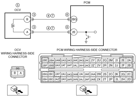
8
|
INSPECT OCV CONTROL CIRCUIT FOR OPEN CIRCUIT
• OCV and PCM connectors are disconnected.
• Inspect for continuity between OCV terminal A (wiring harness-side) and PCM terminal 2E (wiring harness-side).
• Is there continuity?
|
Yes
|
Go to the next step.
|
|
No
|
Repair or replace the wiring harness for a possible open circuit, then go to the next step.
|
|
9
|
VERIFY DTC TROUBLESHOOTING COMPLETED
• Make sure to reconnect all disconnected connectors.
• Clear the DTC from the PCM memory using the M-MDS.
• Switch the ignition to off.
• Start the engine and warm it up completely.
• Perform the KOEO or KOER self test.
• Is the same DTC present?
|
Yes
|
Replace the PCM, then go to the next step.
|
|
No
|
Go to the next step.
|
|
10
|
VERIFY AFTER REPAIR PROCEDURE
• Perform the “AFTER REPAIR PROCEDURE”.
• Are any DTCs present?
|
Yes
|
Go to the applicable DTC inspection.
|
|
No
|
DTC troubleshooting completed.
|