|
1
|
Insert the emergency key in the emergency slot and start the engine.
Does the engine start?
|
Yes
|
Inspect the advanced keyless entry and push button start system.
Repair or replace the malfunctioning part according to the inspection results.
|
|
No
|
Go to the next step.
|
|
2
|
Do any of the following conditions appear?
• Engine does not start completely.
• PCM DTC P1260:00 is displayed.
|
Yes
|
Both conditions are appear:
• Go to Step 5.
|
|
No
|
Either or other condition appears:
• Go to the next step.
|
|
3
|
Inspect the connection of coil antenna connector.
Is the coil antenna connector securely connected to the coil antenna?
|
Yes
|
Go to the next step.
|
|
No
|
Reconnect the coil antenna securely, then repeat from Step 1.
|
|
4
|
Does the security light flash?
|
Yes
|
Go to the next step.
|
|
No
|
Inspect the instrument cluster and the wiring harness.
|
|
5
|
Retrieve the immobilizer system DTC using the M-MDS.
Are any DTCs present?
|
Yes
|
Go to the applicable DTC inspection.
|
|
No
|
Go to the next step.
|
|
6
|
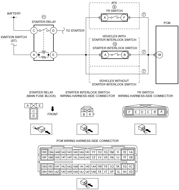
Inspect the following wiring harness and connectors:
• Between coil antenna terminal C and keyless control module terminal 2D
• Between coil antenna terminal D and keyless control module terminal 2B
• Between PCM terminal 1AI and keyless control module terminal 2I
• Between PCM terminal 1AM and keyless control module terminal 2G
Is there any malfunction?
|
Yes
|
Repair or replace the malfunctioning part according to the inspection results.
|
|
No
|
Go to the next step.
|
|
7
|
Inspect the following:
• Battery connection
• Selector lever is in P or N position (ATX)
Are all items normal?
|
Yes
|
Go to the next step.
|
|
No
|
Service if necessary.
Repeat Step 7.
|
|
8
|
Inspect the starter relay.
Is there any malfunction?
|
Yes
|
Replace the starter relay.
|
|
No
|
Go to the next step.
|
|
9
|
Remove the starter relay.
Switch the ignition to ON (engine off).
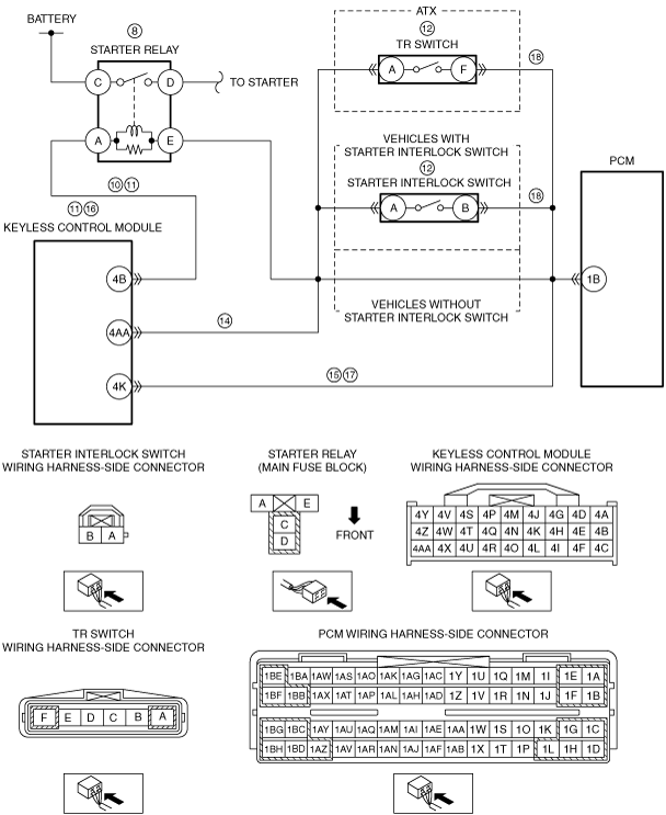
Measure the voltage of the connector terminal (primary coil power supply) on the starter relay terminal A (wiring harness-side).
Is the voltage B+?
|
Yes
|
Go to Step 12.
|
|
No
|
Go to the next step.
|
|
10
|
Switch the ignition to off.
Disconnect the keyless control module connector.
Inspect for continuity between keyless control module terminal 4B (wiring harness-side) and starter relay terminal A (wiring harness-side).
Is there continuity?
|
Yes
|
Go to the next step.
|
|
No
|
Repair or replace the suspected wiring harness and connector.
|
|
11
|
Inspect for continuity between keyless control module terminal 4B (wiring harness-side) and body ground.
Is there continuity?
|
Yes
|
Replace the keyless control module.
|
|
No
|
Repair or replace the suspected wiring harness and connector.
|
|
12
|
Install the starter relay.
Short the terminals of the starter interlock switch connector (2-pin) using a jumper wire (Vehicles with starter interlock switch).
Short the TR switch terminals A and F using a jumper wire (ATX).
Switch the ignition to start.
Does the engine start?
|
Yes
|
Replace the starter interlock switch. (Vehicles with starter interlock switch)
Replace the TR switch. (ATX)
|
|
No
|
Go to the next step.
|
|
13
|
Is the starter relay operation sound heard when the engine starting procedure is performed in Step 12?
|
Yes
|
Go to the next step.
|
|
No
|
Go to Step 17.
|
|
14
|
Switch the ignition to ON (engine off).
Measure the voltage at the keyless control module terminal 4AA (wiring harness-side).
Is the voltage B+?
|
Yes
|
Go to the next step.
|
|
No
|
Repair or replace the suspected wiring harness and connector.
|
|
15
|
Switch the ignition to off.
Disconnect the keyless control module and starter interlock switch (Vehicles with starter interlock switch)/TR switch (ATX) connectors.
Inspect for continuity between the following terminals (wiring harness-side):
• Keyless control module terminal 4K—Starter interlock switch terminal B (Vehicles with starter interlock switch)
• Keyless control module terminal 4K—TR switch terminal F (ATX)
Is there continuity?
|
Yes
|
Go to the next step.
|
|
No
|
Repair or replace the suspected wiring harness and connector.
|
|
16
|
Inspect the following:
• Starter
• Wiring harness between the starter and ground
• Starter power supply (from battery through secondary starter relay, to starter)
Is there any malfunction?
|
Yes
|
Repair or replace the malfunctioning part according to the inspection results.
|
|
No
|
Replace the keyless control module.
|
|
17
|
Switch the ignition to off.
Disconnect the keyless control module and starter interlock switch (Vehicles with starter interlock switch)/TR switch (ATX) connectors.
Inspect for continuity between the following terminals (wiring harness-side):
• Keyless control module terminal 4K—Starter interlock switch terminal B (Vehicles with starter interlock switch)
• Keyless control module terminal 4K—TR switch terminal F (ATX)
Is there continuity?
|
Yes
|
Go to the next step.
|
|
No
|
Repair or replace the suspected wiring harness and connector.
|
|
18
|
Starter interlock switch (Vehicles with starter interlock switch)/TR switch (ATX) connector is disconnected.
Disconnect the PCM connector.
Inspect for continuity between the following terminals (wiring harness-side):
• PCM terminal 1B—Starter interlock switch terminal B (Vehicles with starter interlock switch)
• PCM terminal 1B—TR switch terminal F (ATX)
Is there continuity?
|
Yes
|
Go to the next step.
|
|
No
|
Repair or replace the suspected wiring harness and connector.
|
|
19
|
Inspect for a seized/hydro locked engine or flywheel (MTX) or drive plate (ATX).
Is the engine seized or hydro locked?
|
Yes
|
Go to the next step.
|
|
No
|
Repair or replace components if required.
|
|
20
|
Retrieve any continuous memory DTCs using the M-MDS.
Are there any continuous memory DTCs displayed?
|
Yes
|
Continuous memory DTC is displayed:
• Go to the applicable DTC inspection.
Communication error message is displayed:
• Open circuit in wiring harness between main relay terminal B and PCM terminal 1AT
• Open circuit in wiring harness between main relay terminal C and PCM terminals 1BE, 1BF
• Main relay is stuck open.
• Open or short circuit in wiring harness between DLC-2 and PCM terminals 1AM and/or 1AI
• Open or poor ground circuit (PCM terminals 1AZ, 1BB, 1BD, 1BG and 1BH)
• Poor connection of vehicle body ground
|
|
No
|
Go to the next step.
|
|
21
|
Perform the KOEO self test.
Are there DTCs displayed during the KOEO inspection?
|
Yes
|
Go to the applicable DTC inspection.
|
|
No
|
Perform the advanced keyless entry and push button start system symptom troubleshooting “NO.3 PUSH BUTTON START SYSTEM DOES NOT OPERATE”.
|
|
22
|
Verify the test results.
• If a malfunction remains, inspect the related Service Information and perform the repair or diagnosis.
-
― If the vehicle is repaired, troubleshooting is completed.
|